Will do! I have to call RCR tomorrow to order some things and hopefully they can give me access to the manual. I have a manual on CD but I’m sure it’s extremely outdated.Congratulations on getting her home. Let the fun begin!!
Love the wheels! Traction may be an issue with those tires though, LOL.
I did not see anything in your pics that jumped out at me as an issue. Others may be able to critique further.
Your starting point for assembly sounds good. Be sure you get access to the manual online from RCR and read it at least twice. I would suggest you put together a build schedule of the order you plan to do things. Reading the manual will help with this. I would also suggest generating a bill of materials to track what you need to purchase for the car and what you have purchased.

- Forums
- GT40 Replica Manufacturers' Corner
- RCR Forum - RCR40/SLC/917/Superlite Aero
- The SLC Clubhouse
You are using an out of date browser. It may not display this or other websites correctly.
You should upgrade or use an alternative browser.
You should upgrade or use an alternative browser.
Converting RHD SLC to LHD
- Thread starter SoFlo
- Start date
Congrats Kyle, looking forward to seeing the progress. Only thing that Looks different to me is there are washers right under the steering rack Between it and the frame/tub. Newer cars have no washers and some older cars have spacers.
Happy to answer any questions.
Interesting, I just looked at the picture, I hadn’t noticed before.
Scott is shipping me his LHD rack, hopefully that will be here later this week so I can get things sorted there.
Joel you’re using an LT4? Is that the same engine mount as the LS? If I can’t find a used engine mount then I’ll be purchasing from RCR.
Another difference I noticed from Kurts build is that he has two large brackets mounted on the lower rear frame that I assume mount the rear clam. I don’t believe I have those. Maybe I have an earlier design.
Kyle,
The two large brackets you see on my build are the latest version of the rear clam hinge that limit how far the clam opens. It appears from your pictures that you have the earlier version of the rear clam hinge. The new version is available from RCR or you can use what you have and add a method to limit how far the clam opens so it does not hit the ground.
The two large brackets you see on my build are the latest version of the rear clam hinge that limit how far the clam opens. It appears from your pictures that you have the earlier version of the rear clam hinge. The new version is available from RCR or you can use what you have and add a method to limit how far the clam opens so it does not hit the ground.
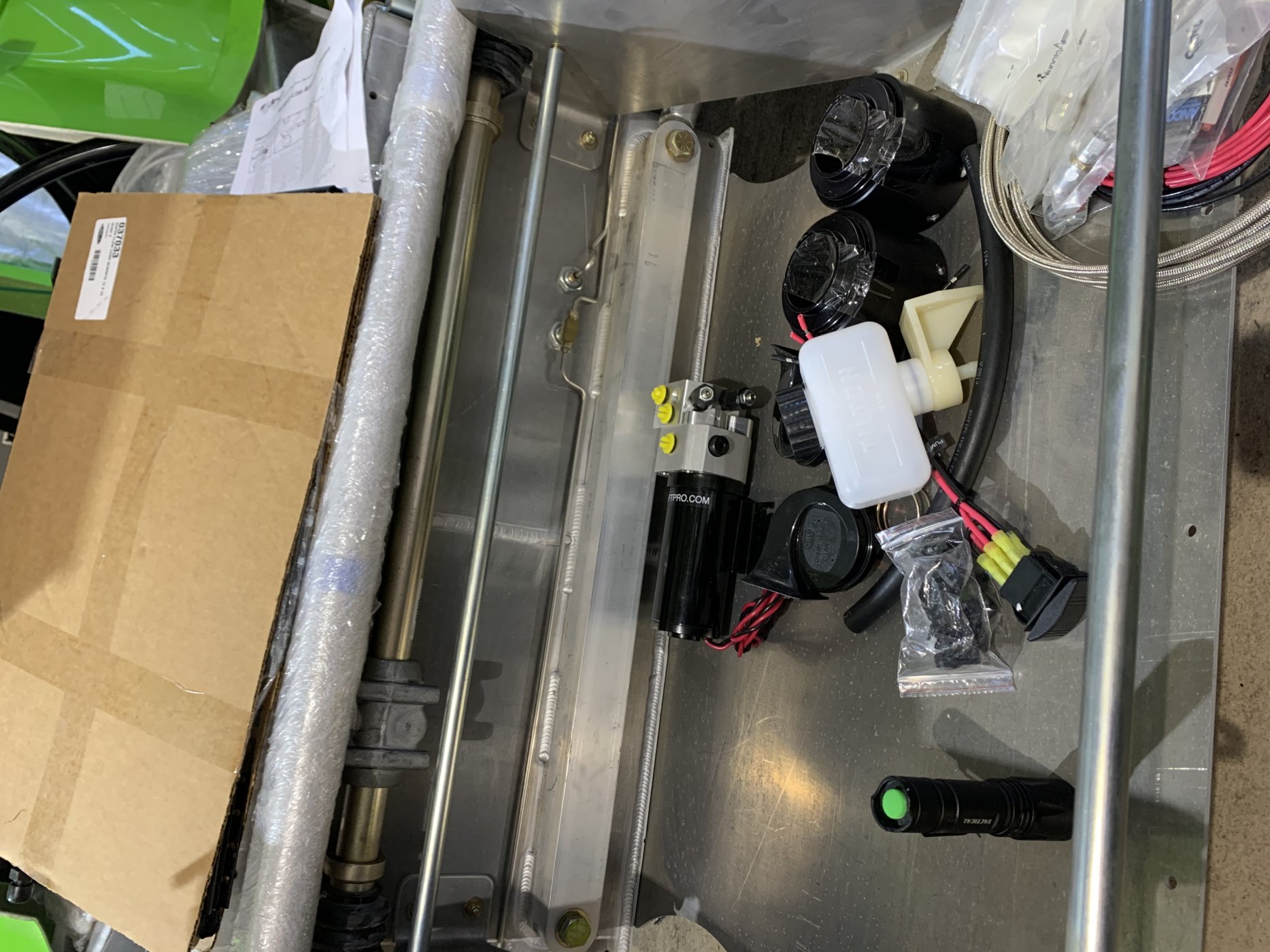
Can anyone spot the problems here.....
aside from my photos being turned every time, which I have no idea how to fix....
Remember this car was purchased 5 years ago and sat, not a single hole drilled, nothing. As you can see it was set up for RHD yet all the brake lines are on the left side, you can also see the fuel tank won’t work at all, the hole down the middle is set for RHD yet they have the fuel pump inlets on the wrong side. Also, the tub is a LHD tub....my frustrations are growing with problems created from the factory. These are all major issues that I am out of luck on because the factoring messed up and no one bothered to check.
Attachments

Last edited:
Joel K
Supporter
Hi Kyle,
First thing, take a deep breath. All this can be worked through. Every build has its set of challenges. You will have a few extra due to this being a RHD car, but nothing insurmountable. We all run into certain issues based on what we are trying to create. My suggestion is taking each problem one at a time and thinking through multiple ways to solve it, ask the forum for input as well and at some point you will know when the right approach is found and then implement it.
In my case, if I try to solve all the issues at once it is not fun nor effective. I like focusing on one or two issues at a time, coming up with the solution, implementing it and moving on. Each problem solved is a sense of accomplishment. Part of the enjoyment of building the SLC.
Here are some initial thoughts...
1)when the photos uploaded are rotated. I edit them on my iPad rotate once and save. then rotate them 3 more times and save again. Then when uploading them the orientation is fine.
Here you go....


2)with regard to the fuel tank, can you simply slide it over and run elbows out the back and have the fuel system components outside the fuel area where most people put it? Or, use an in tank fuel pump, which I did(Ken and Johan also) and then you have no reason to have those side bungs and can weld them up. Or, cut open the fuel tank and move the center tube, have a professional welder weld it up. Not a big deal.
3)with regard to brake lines, many builders run the brake lines inside the tub, so if this was going to be built as right hand drive, the brake lines would have been run to the bulkheads inside the car. Many of the build threads on the forum show brake lines inside the footbox. Also, many builders choose to fabricate their own brake lines because they want to route them differently. I plan to use some of what is in the kit, but not all.
4)The tub is just fiberglass, easy to splice it up into sections and re-work it. if you haven’t done fiberglass work, just one more skill set to develop. I am planning to section the tub up so I can remove the fuel tank panel,
Hopes this advise helps.
First thing, take a deep breath. All this can be worked through. Every build has its set of challenges. You will have a few extra due to this being a RHD car, but nothing insurmountable. We all run into certain issues based on what we are trying to create. My suggestion is taking each problem one at a time and thinking through multiple ways to solve it, ask the forum for input as well and at some point you will know when the right approach is found and then implement it.
In my case, if I try to solve all the issues at once it is not fun nor effective. I like focusing on one or two issues at a time, coming up with the solution, implementing it and moving on. Each problem solved is a sense of accomplishment. Part of the enjoyment of building the SLC.
Here are some initial thoughts...
1)when the photos uploaded are rotated. I edit them on my iPad rotate once and save. then rotate them 3 more times and save again. Then when uploading them the orientation is fine.
Here you go....
2)with regard to the fuel tank, can you simply slide it over and run elbows out the back and have the fuel system components outside the fuel area where most people put it? Or, use an in tank fuel pump, which I did(Ken and Johan also) and then you have no reason to have those side bungs and can weld them up. Or, cut open the fuel tank and move the center tube, have a professional welder weld it up. Not a big deal.
3)with regard to brake lines, many builders run the brake lines inside the tub, so if this was going to be built as right hand drive, the brake lines would have been run to the bulkheads inside the car. Many of the build threads on the forum show brake lines inside the footbox. Also, many builders choose to fabricate their own brake lines because they want to route them differently. I plan to use some of what is in the kit, but not all.
4)The tub is just fiberglass, easy to splice it up into sections and re-work it. if you haven’t done fiberglass work, just one more skill set to develop. I am planning to section the tub up so I can remove the fuel tank panel,
Hopes this advise helps.
Well said Joel. Every problem has multiple solutions, you just need to sort through all the scenarios and pick the most logical one for you.
Regads Brian
Regads Brian
Hey guys I realize my post may have come off a bit harsh! I guess what I’m trying to express is that I’m surprised there were this many mistakes from the factory. If I were the first owner I would have been very unhappy.
Plans are to move the pass through pipe in the tank. Cut out the center section of the tub and reglass. Brakes are fine as is since I’m going LHD anyways. Steering rack should be here Monday and trans and motor adaptor. Hopefully I can make more progress next week.
Plans are to move the pass through pipe in the tank. Cut out the center section of the tub and reglass. Brakes are fine as is since I’m going LHD anyways. Steering rack should be here Monday and trans and motor adaptor. Hopefully I can make more progress next week.
Have a peek inside the tank from the sender hole to see if there are 2 cross through tubes. It almost looks like they built a complete left hand tank and then they welded up the original tube with end plates. If that's the case it would be an easy fix to open it back up. Either way you might want to consider some type of modification anyway to improve the slosh issues.
Grinded out the tube and the other hole, I’ll order a new one and reposition. Shouldn’t be as bad as I thought.


Polished up the suspension, amazing how much it shines. I’m painting the calipers and rotors currently.

In the next pic you can see how I’m mocking up my engine mount. There’s more to it but you get the point. Just need the adaptor before i can weld everything up. The hex rod will be tapped and threaded. The angle will sandwich the aluminum tubing as well.
.

Also i took a peek in the box with the shifter. Is this the same shifter used with the G96? It is labeled 91 and 93.


Polished up the suspension, amazing how much it shines. I’m painting the calipers and rotors currently.
In the next pic you can see how I’m mocking up my engine mount. There’s more to it but you get the point. Just need the adaptor before i can weld everything up. The hex rod will be tapped and threaded. The angle will sandwich the aluminum tubing as well.
.
Also i took a peek in the box with the shifter. Is this the same shifter used with the G96? It is labeled 91 and 93.
Howard Jones
Supporter
Do you have a gearbox, driveshafts/CVs and engine yet? If not wait until you do before making and welding in motor and gearbox mounts. These mounts need to be pretty much dead on and it is way easier to use the actual powertrain as a fixture for making them correct the first time.
You do not want to repeatedly cut and weld on the chassis tubing. First time correct and done by a person who has experience with 4041 T6 aluminium tubing is very important. Every time you weld it, it loses it's heat treatment locally to the welding paths. Once done correctly is the best way to prevent weakening the structure. Don't freak out about this, just read up on the subject and then have someone knowledgeable do it right for you.
Another bit of advice. Throughout the entire build do everything possible so as not to drill unnecessary holes in the chassis tubing, especially in the rear tubing structure. If you need to mount something necessary then do it but try and use mounting points for more than one thing. Remember every hole is a stress riser. I spent a LOT of time trying to minimise drilling holes in the chassis tubes. Again don't freak out about this, just slow down and think things through before you drill and cut things that can't be undone.
Do you have a gearbox, driveshafts/CVs and engine yet? If not wait until you do before making and welding in motor and gearbox mounts. These mounts need to be pretty much dead on and it is way easier to use the actual powertrain as a fixture for making them correct the first time.
You do not want to repeatedly cut and weld on the chassis tubing. First time correct and done by a person who has experience with 4041 T6 aluminium tubing is very important. Every time you weld it, it loses it's heat treatment locally to the welding paths. Once done correctly is the best way to prevent weakening the structure. Don't freak out about this, just read up on the subject and then have someone knowledgeable do it right for you.
Another bit of advice. Throughout the entire build do everything possible so as not to drill unnecessary holes in the chassis tubing, especially in the rear tubing structure. If you need to mount something necessary then do it but try and use mounting points for more than one thing. Remember every hole is a stress riser. I spent a LOT of time trying to minimise drilling holes in the chassis tubes. Again don't freak out about this, just slow down and think things through before you drill and cut things that can't be undone.
Yes my motor/trans has been waiting patiently for a few months. Currently waiting on the adaptor and flywheel from RCR. Thats a big sticking point for my right now. Also waiting on a few other parts so I can finish up the brakes.
I fit the tub today but I’m still not quite sure what’s going on. I modified the tub and it fits nicely but I’m not sure where the “bottom point” of the tub is. I’m having a problem with my body being way too high. It’s either the tub I have to drop down more or trim the spider, neither of which I though was necessary. Any advice?
You do not want to repeatedly cut and weld on the chassis tubing. First time correct and done by a person who has experience with 4041 T6 aluminium tubing is very important. Every time you weld it, it loses it's heat treatment locally to the welding paths. Once done correctly is the best way to prevent weakening the structure. Don't freak out about this, just read up on the subject and then have someone knowledgeable do it right for you.
Another bit of advice. Throughout the entire build do everything possible so as not to drill unnecessary holes in the chassis tubing, especially in the rear tubing structure. If you need to mount something necessary then do it but try and use mounting points for more than one thing. Remember every hole is a stress riser. I spent a LOT of time trying to minimise drilling holes in the chassis tubes. Again don't freak out about this, just slow down and think things through before you drill and cut things that can't be undone.
I can second what Howard says here. I am doing major modifications to the chassis, and in the end I will be welding a single aluminum cross member in the rear. Everything else will be bolted using the stock holes. I am not doing the welding myself. My first thoughts when I got my chassis was to start drilling and welding, but after alot of prototyping I can see it was not necessary. There are lots of ways to solve issues on these cars. I am learning the fastest way might not always be the best.
Bob
Howard Jones
Supporter
At the front L and R interior corners of the center body section where it droops over the top corners of the aluminum foot box:
Check and see if there is excessive fiberglass material in these corners that prevent the fiberglass from fitting snugly and level. If so carefully remove as much as is necessary to get a good fit across the front of the center body section where it sets on the top of the foot box. Some fitting may be necessary along the inside edge here also.
A good fit in this area will allow the center body section to sit nice and snug on the chassis. This will also help with the height the body sets on the chassis overall. Don't go crazy just remove enough to get a good fit.
Elsewhere: Heres my 2c's. The body should set a low as possible on the chassis in all cases. The tubs placement should be secondary to this goal. Fit the center section onto the chassis with the tub out of the way. Remove a bit of fiberglass in the areas as I mentioned above and elsewhere where it sets on the chassis. Then add shims so that it set firmly on the chassis. Use big flat shims so that the fiberglass has lots of surface area to set on I used aluminum flat stock as much as 3/8 inches thick and cut to fit the placement point. The ones on the shoulders of the rear chassis where the beer car holders are were 3/8 X 2 X 6 or so. A nice flat mating point for the body to set on is what you want. Fix the shims in place. I used rivets Don't drill body mount holes yet.
Now check out where the tires and wheels are placed and how they fit. Once you have the tires and wheels in on the car with the suspension aligned and the body placed so as to accommodate the tires as best as is possible you now check the windshield fit but do now install it with glue, The windshield MUST FIT before you go further! Do not bend or attempt to force the windshield to the body IN ANY WAY! NOT EVEN A 1/8 inch. NONE!!!!! The body must be made to fit the windshield before you finalize the center section placement. The glue will fix up to 1/4" of a gap but as little as possible of a gap around the windshield is the goal. An 1/8 " will be OK.
Now that the windshield fits into the body center section, check the tires and wheels fit again. If the windshield and the tires are good to go NOW you can mount the center section by drilling and threading holes thru the shims and using the bolts that are necessary.
Take as much time as necessary to get this part right.
Once you are at this point you can remove the center section at will and it will always aline itself back onto the chassis in a placement that the windshield will fit nicely into.
I would do the doors next. And then............................
Now you can go back to the interior components such as the tub and make them all fit the indexed center section location with the doors mounted
The windshield is THE KEY TO THE BODY PLACEMENT ALONG WITH THE TIRES. Everything else should be altered to accommodate that.
That's what I think...............My way isn't the only way I'm sure as others all have opinions also, but going back after the entire body is on the car and trying to make the windshield fit is a nightmare. Several have been broken. So have a good think, go slow, and have fun.
Last edited:
and trying to make the windshield fit is a nightmare.
Not if you're smart and use the lexan windshield ... SOB fits however I tell it to fit, haha!
Similar threads
- Replies
- 26
- Views
- 8K
- Replies
- 7
- Views
- 6K