
You are using an out of date browser. It may not display this or other websites correctly.
You should upgrade or use an alternative browser.
You should upgrade or use an alternative browser.
Gullwing Door Conversion
- Thread starter Heinrich
- Start date
Hi Guys
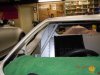
Apologies for the delay in the update. Worked on the door fitment with fibreglass etc and now have them seating with equal gaps. With the actuator pulling down at the back we found that the doors slightly buldges as it closes. Busy making some locating pins but as it comes down in an arch, these pins have to be at 42 degrees on the door cill and of course the door. Tested and works fine and the final seating adjustment will be made on them as the door closes that last 10 mm.
Looking at the thread, the electric latch seemed an option .... but think I have found a good solution, an electric magnetic lock. Found a small one, some 170 long, 40 wide and 30 high with some 150kg "pull". It works like a charm, as the door starts to guide in the locating pins, the mag lock does a pull motion down and thus stops the actuator having to force / pull down. Will sort out the electic's to on/off the mag lock once we have all working.
Should have the one door all mounted by the weekend and will then post some pic's.
In the meanwhile busy prepping the rear for painting... dust everywhere.
Will post on the sliding windows as there we are also making progress.
Regards
Heinrich
Heinrich,
Be sure to take detailed shots of the door closing/locking mechanism. I am fighting with myself as to what type of mechanism I want(from the outside). The traditional mechanism is difficult to get into the door(for me anyway), so I am looking at electrical latch systems. Would be interested in what you have come up with. I am using a Toyota inside door opening handle with the long rods and bell crank to open the door. The handle is on the lower front part of the door for easy access like this one here.

Bill
Be sure to take detailed shots of the door closing/locking mechanism. I am fighting with myself as to what type of mechanism I want(from the outside). The traditional mechanism is difficult to get into the door(for me anyway), so I am looking at electrical latch systems. Would be interested in what you have come up with. I am using a Toyota inside door opening handle with the long rods and bell crank to open the door. The handle is on the lower front part of the door for easy access like this one here.
Bill
Hi
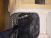
Some progress, have the "draft" pins and guides fitted with a "magnetic lock" system to assist with the last alignment and securing the door. It is a 150 lbs lock so it holds the door securely in its pins. The angle at which the pins and guides are astounded me as one does not realize the accute angle - based on the raduis of the gullwing hinge.
Will now neaten up and start with final fitment - that is once I have the glass windows in (see seperate thread). Will be turning some bright metal pins to secure the actuator with release pins should I have power or mechanical failure on the actuators.
Regards
Heinrich
Attachments
Hi
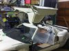
OK, so the 8" actuator I have is causing some problems. With the short stroke it meant placing the push point some 5.75 " from the hinge point. (Based on a 90 degree opening) This works but a lot of stress on the hinges as the "point of attack" is to close to the hinge point and found that the one hinge has twisted.
Plan B - found tubular actuator with a 18" stroke thus can place the push point some 13" from the hinge and the actuator now stands just about vertically and connects to the door about 90 degrees. Should solve problem as the angle of attach is now less.
See attached rough drawing of the problem and the new position of the 18" actuator.
Picture of the current 8" illustrates how accute the push angle and how close the push point is to the hinge which off course makes the force required to open the door x 8 at least.
Hopefully install the new 18" in the next couple of days and give some feed back.
Regards
Heinrich
Attachments
Hi
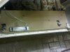
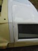
Some feedback on the slow progress of the gullwings. The new 18" actuators work great and look much better than the shorter ones. Their mounting position is much better and not above/behind the head space. Had to cut a small wedge out of the door at sil level internally in order to mount.
Started making new hinges to fit into the "autoloc" recepticals in order not to have to re-engineer what has been done. Only problem is that it will mean that each door will have two small - about 2" x .5" (50x12 mm) hinge sections protruding above the door. The new hinges work perfectly and are solid with no play in the hinges. But not 1st prize as they protruded above the door (which with the intention to go white with a black stripe across the roof - can be "hidden" in the black stripe)
The problem with the Autoloc hinges was the play / movement within the hinges. Some more than others - so started to try and find the cause of this development and found the following "problems"
1. The old actuators being so close to the hinge point and the force on the hinge casued it to strecth ever so slightly - this has been resolved with the new 18" actuators.
2. On closing, when we made the spyder and door recipticals and welded/glassed them into the door and spyder, they are ever so slightly past the 180 degrees. So on closing, the hinge streched just beyond its normal closed position.
The combination of the above is that all 4 hinges now are slightly damaged/twisted/strecthed. We dissasembled the hinges and repaired as far as possible and with the best 2 of the 4 found that the play/movement over the span of the door of some 4 feet is acceptable and the door slides into the bottom guides.
We had to modify the hinge mounts at a slight angle so that when the door closes past the 180 degrees - the hinge does not past the normal closed position.
So, all systems go with the Autolock hinges at this stage as they are hidden and do not protude above the door.
The Autolock hinges mechanics are simple but the actual working parts metal is not that great - so in the process of making our own replacement parts out of harder metal and pins which we found to be soft and easily bent.
I will post some pics in the next couple of days with the new actuators and the slide down glass windows.
Regards
Heinrich
Hi Guys
Herewith an update on the gullwing project. I have now installed the "Firgelli" longer actuators and new hinges from Autocloc. The actuator has a longer travel of 18" and realy work well.
The new hinges from Autolock are much better quality and are now stable. Currently busy with the body work alingment and a dusty business as we all know. The Maglocks work great and the electrics all sorted.
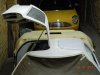
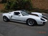
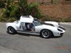
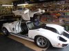
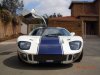
As can be seen from the pictures, the car is parked about 18" from the wall and the door opens with olenty space to spare... does solve some parking problems !:lipsrsealed:
Here some pictures
Regards
Heinrich
Herewith an update on the gullwing project. I have now installed the "Firgelli" longer actuators and new hinges from Autocloc. The actuator has a longer travel of 18" and realy work well.
The new hinges from Autolock are much better quality and are now stable. Currently busy with the body work alingment and a dusty business as we all know. The Maglocks work great and the electrics all sorted.
As can be seen from the pictures, the car is parked about 18" from the wall and the door opens with olenty space to spare... does solve some parking problems !:lipsrsealed:
Here some pictures
Regards
Heinrich
Attachments
Hi Randy
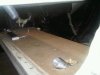
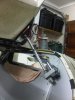
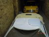
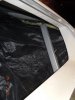
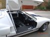
I have taken some pic's that kind of shows the actuators. Unfortunately with me busy with the body work, everything is taped up.
The driver side is perfect as the sil with the gearlever is wider and thus the seat is more offset to the centre and the seat fits with out any modifications. The actuator is close to the bulkhead and when closed it sits right next to the seat and I found no obstruction when sitting in the car.
On the passenger side, I need to slightly modify the seat or move it forward about 1 inch. That way it will sit just behind the seat on the corner.
Hope these pic's show what I am trying to explain
Regards
Heinrich
Attachments
ah, here is more the principle wich I thought of could probably work for those light doors...


also the old 300sl uses that sort mounting way of the cillinders only uses 2

So the Delorean uses just one cillinder, it also has that special little window in window what you can make in a GT40 door if you don't want the normal type I guess...
DeLorean Page 1
also the old 300sl uses that sort mounting way of the cillinders only uses 2
So the Delorean uses just one cillinder, it also has that special little window in window what you can make in a GT40 door if you don't want the normal type I guess...
DeLorean Page 1
Hi
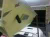
In the prior posts you will note the shorter actuators, but they had to short a stroke and were mounted as per the pics. The short stroke put big pressure on the hinges and damaged them. Ideally it would be great to go the Merc route but mounting the 2 gas shocks or actuators becomes a problem in where to do it in the fibreglass.
Strengthening the roof center section was a mission but now I can sit on the centre. The two gas shocks are a challenge with the door top corners being "round"....
But, yes, something to look at as plan G :uneasy:
Attachments
I think those are also to big...
also I think you could do it with one pressure cylinder, you can get those cheap in with any pressure you want...
you can use the mounting point as per last 2 pictures on the door, but put the other side as high as possible in the cabin near to the roof when there somewhere is a point to mount the pressure cylinder, I see there rivets so you have a mounting point posibility there.
then you have just small pressure cylinders one on each door, they come in any strenght you like...but begin with low pressure otherwise it damage the door.
this type, they are thin and need little room but can be very strong if you wish, you only have to know how strong/weakneed them, how much weight they have to push or hold
http://www.carpartswholesale.com/v5/?Ntt=monroe+lift+support+901456
also I think you could do it with one pressure cylinder, you can get those cheap in with any pressure you want...
you can use the mounting point as per last 2 pictures on the door, but put the other side as high as possible in the cabin near to the roof when there somewhere is a point to mount the pressure cylinder, I see there rivets so you have a mounting point posibility there.
then you have just small pressure cylinders one on each door, they come in any strenght you like...but begin with low pressure
otherwise it damage the door.this type, they are thin and need little room but can be very strong if you wish, you only have to know how strong/weakneed them, how much weight they have to push or hold
http://www.carpartswholesale.com/v5/?Ntt=monroe+lift+support+901456
Last edited:
Hi Guys
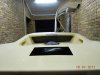
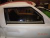
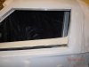
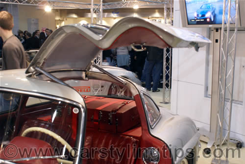
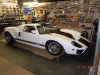
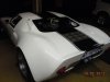
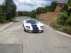
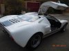
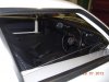
Apologies for not posting awhile.... but my baby is on the road. Here are some pics of the gullwing doors and the windows.
Will now be driving it a little while and sort out minor problems... (as always). The doors work well and the windows are an absolute must.
Next is paint work that needs some touch up and final polish and then upholstery.
Regards
Heinrich
Attachments
Ian Anderson
Lifetime Supporter
What superb clean lines it gives without the door handle!
Well done
Ian
Well done
Ian
Looks like a seamless nostril panel too....very slick
Eventually the paint work has been sorted and the upholstery done.
Enjoying every minute driving it, windows work well and a pleasure to have a breeze in the cockpit.
Enjoying every minute driving it, windows work well and a pleasure to have a breeze in the cockpit.
Attachments
Similar threads
- Replies
- 14
- Views
- 5K
- Replies
- 8
- Views
- 3K
- Replies
- 17
- Views
- 14K