I need help - How do you adjust / setup / balance your ITB / 8-Stack?

Markus

SPRF40
Lifetime Supporter
Hello from Germany,

I experienced some engine issues (http://www.gt40s.com/forum/gt40-tech-engines-induction-exhaust/43096-roush-353ir-accel-dfi-ecm-file-needed.html#post441397) and finally (after searching the forum) checked the throttle adjustment via air flow meter and did not like what I found.
After playing with the adjustment I saw changes (good and bad) and finally had some huge improvements.
On the Roush website I found an "Installation Manual" which helped a lot during adjustment: http://www.roushperformance.com/engines/manuals/R21180001-10-AA-8-STACK-EFI-Instructions.pdf

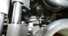
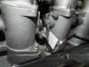
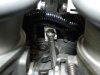
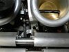
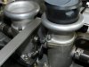
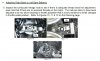
However I still have issue when trying to tighten the turnbuckle style linkage rods like described in the Roush manual:

“With the linkage rods at an adequate length, snug both lock screws at the ends of the left bank rod in a position that does not put the ball ends into a bind. The locked rod should be able to twist back and forth about 1/6” of a turn or more.”

My problem is:
I get the airflow right or the alignment of the ball ends.

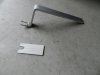
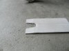
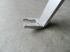
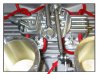
I’m not able to get both right at the same time. Currently I’m fabricating a “ball end alignment tool” so they don’t bind during tightening the lock nuts on both ends. The tool works like a fork to keep the two ball ends aligned (one horizontally, the other vertically).

How do you make the adjustment on your ITB or particular how do you retighten the linkage rods without forcing the ball ends into a bind and keep them horizontally and vertically aligned?

Thank you in advance.

Markus

P.S. I don’t tell you what parts I have already changed before looking into the basic things……
… but like usual, when finding the right thread you find a solution, it’s all there
http://www.gt40s.com/forum/gt40-tech-engines-induction-exhaust/26633-developed-mis-under-load.html
Thank you people in the forum!
 

Terry Oxandale

Skinny Man
I wished I could help, but I struggle with the same issue with both the throttle linkages and with tie-rod suspension arms (which the GT suspension has a lot of)
 
Markus,
You cannot set your ITB,s with just the linkage...you have to disconnect the 2 rods from the central pivot... I use a motorbike 4 meter set up...50euro... that I have calibrated using a known vaccum... individually set your ITB,s one by one using the vaccum from the inlet manifold...one bank off 4 then the other bank off 4...then you adjust your 2 rods to the central pivot & reconnect the throttle linkage...don,t get all confused by the instructions ...you,ll never set them properly...have a look on u-tube.
hope this helps.
Cheers Eddie.
 
Marcos most linkages will pull in the tread when you tighten them, the courser the thread the worse it is.
I use small rose joints with L and R/H threads.

The way I adjust is I disconnect the linkages. I set the throttle stops for idle speed, adjusting till they all read the same on the nanometer.
I connect the linkages and then set the throttle to 1500 rpm and adjust the linkages so I get the same readings or close to it.

If linkages are of poor design or quality you will never get it.

Jim
 

Markus

SPRF40
Lifetime Supporter
Eddie, Jim,

Thanks for your feedback.

When I follow the Roush instructions the result is very even between the individual throttle's.
My problem starts when I have everything properly setup and try to retighten the center linkage rods (left/right thread). While tightening the lock nuts on both ends I get a misalignment of the ball ends (rose joints).
During idle speed that does not matter but when opening the throttle it comes to bind condition within the center linkage which leads to forcing eventually the left and right bank out of sync.....

Due to the inside fuel rails there is also not too much space to work on the center linkage - or to disconnect the linkage.

Nevertheless I will follow your suggestion and try to disconnect the linkage and setup the throttle this way.

I'll keep you updated.

Markus
 
Markus,
A little tip...I always allign my rods with their relivant fixing , then tighten them OFF the central pivot...It may take a few goes to get them correct...with the left & right threads... but I find in the long run it,s better...check you do not have to much upward or downward angle on the rods to your central pivot & that,s causing the bind.
Cheers Eddie.
 

Markus

SPRF40
Lifetime Supporter
Eddie, Jim,

Thanks again.

Finally disconnecting the linkage made the difference.

I only disconnected the linkage from the center pivot. For aligning the ball ends I finished the tool I had started - see pics.
1. The two tools I made
2. Fork for vertical alignment on throttle body
3. Fork for horizontal alignment on center pivot
4. Alignment of ball end on throttle body (outside)
5. Alignment of ball end on throttle body (inside)
6. Alignment of ball end on center pivot (inside)
7. Alignment of ball end on center pivot (inside)
8. Alignment of ball end on center pivot (outside)
Today’s test drive showed big improvement but some things are still not right – seem to be the injection itself….
Markus
 

Attachments

  • DSCN8502 small.jpg
    DSCN8502 small.jpg
    200.8 KB · Views: 299
  • DSCN8503 small.jpg
    DSCN8503 small.jpg
    386.7 KB · Views: 321
  • DSCN8504 small.jpg
    DSCN8504 small.jpg
    399.8 KB · Views: 258
  • DSCN8505 small.jpg
    DSCN8505 small.jpg
    168.5 KB · Views: 338
  • DSCN8507 small.jpg
    DSCN8507 small.jpg
    423 KB · Views: 320
  • DSCN8508 small.jpg
    DSCN8508 small.jpg
    237.9 KB · Views: 324
  • DSCN8509 small.jpg
    DSCN8509 small.jpg
    270.8 KB · Views: 341
  • DSCN8511 small.jpg
    DSCN8511 small.jpg
    321.5 KB · Views: 334
Markus, When I look at pictures 4 & 5 off your central pivot, you have what we call over centre pivots...meaning your rods are to near 12 o,clock to permit smooth action of the control rods..ie...if you draw a line through the center of the pivot at 90deg. to your TB,s the bolt hole for the actuating rod is to near 12 o,clock & should be nearer 2 o,clock...your central pivot is trying to push your rods from to near a straight line....move them by redrilling the holes, use shorter rods & make the rods 90deg. with the mounting on your TB,s.
Cheers Eddie.
 

Markus

SPRF40
Lifetime Supporter
Eddie,

I was looking also into this topic but all information I had did not indicate a problem with the current setup.

Like described in the Roush manual (see pic) and various pictures of TMW ITB setup's (second pic from TWM website) show similar settings!?.

Changing the setup would make it then (even) more sensitive?

Markus
 

Attachments

  • Roush manual.jpg
    Roush manual.jpg
    307 KB · Views: 365
  • TWM.jpg
    TWM.jpg
    107.2 KB · Views: 413
Markus,
I understand what you are saying...fig 10 to me looks about perfect...the rods are straight & the pivots are at 1 o,clock...remember you have 8 throtle bodies, any kind of pedal movement will make the engine sound sensitive...personnally I have mine set up this way & love the short movement.
Eddie.
 

Terry Oxandale

Skinny Man
I've got mine where the rods almost touch the center post (right-side attachment above). It makes for an extremely docile off-idle performance and character. With that set-up, I only get in trouble when I intentionally bury my foot into the pedal, where before, it was a little touchy (i.e figure 10).
 
Back
Top