Jason's Coyote Powered RCR40 Downunder

Thanks Kalun, I will see about the rack when Fran gets some info on the situation.

FITTING BODY PANELS

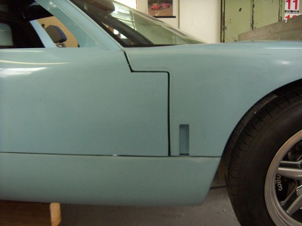
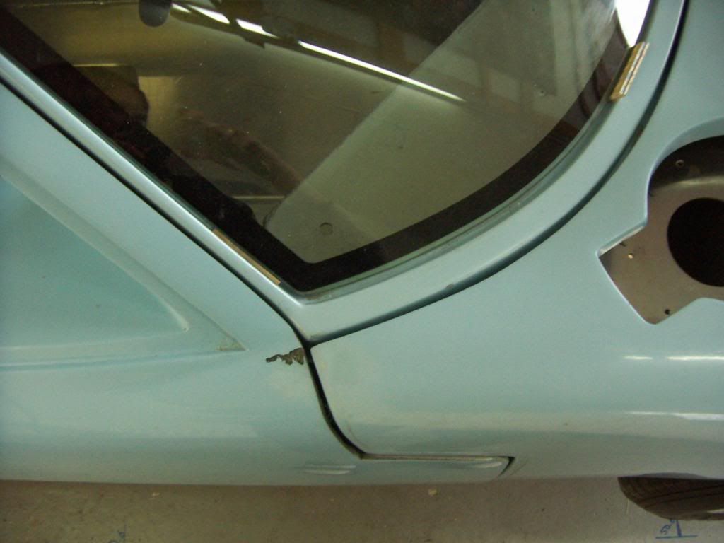
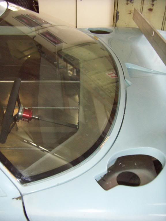
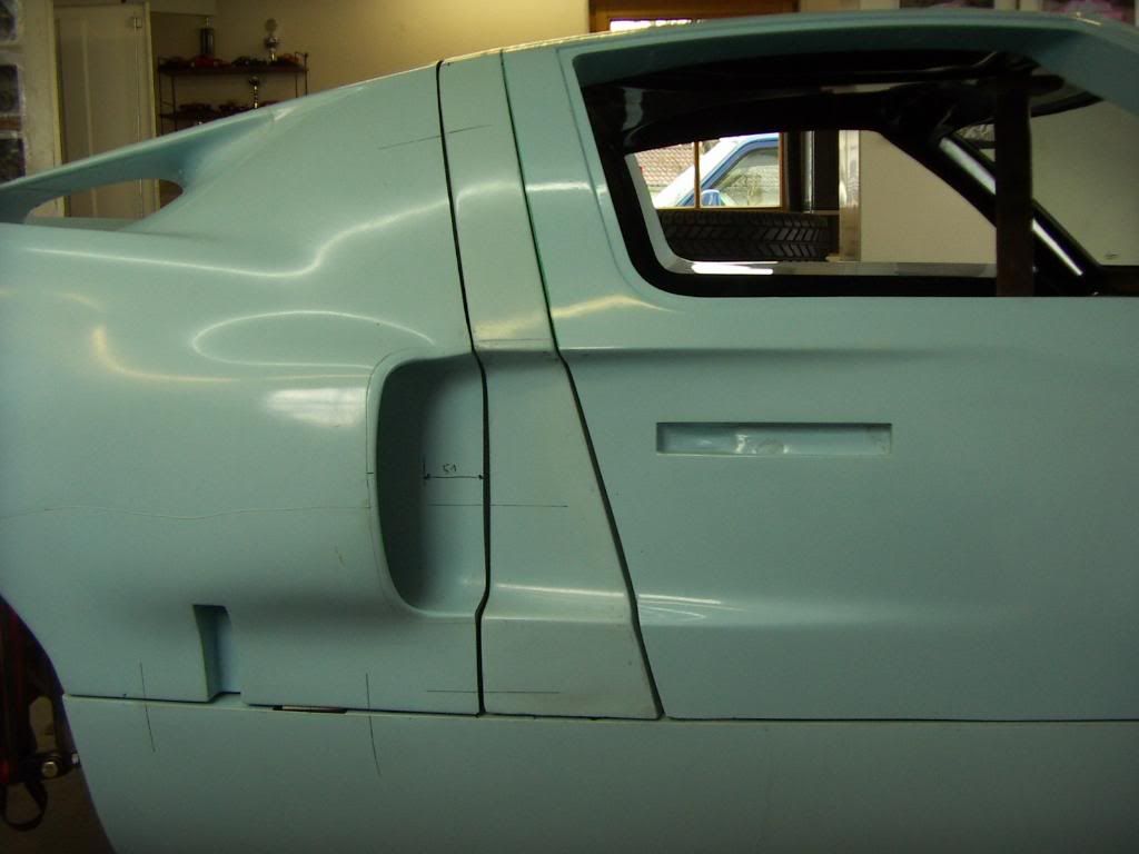
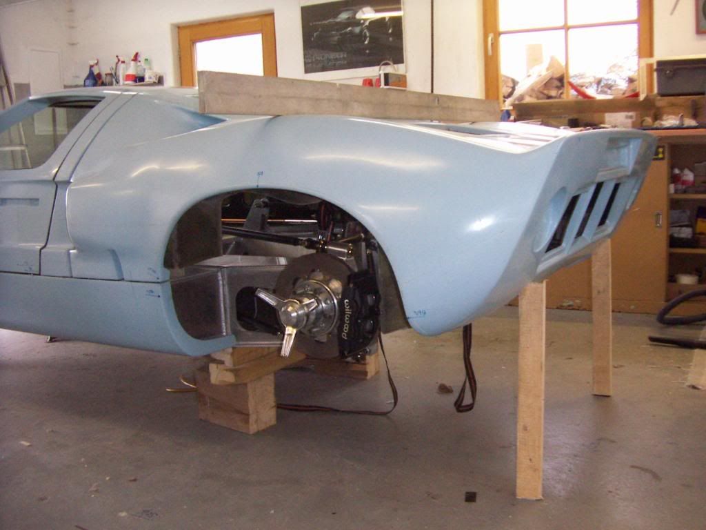
I have kept moving on the build. After loosely fitting the LH & RH rocker panels I fitted the front clip. I have to do some bobbin adjustments to get this right as it sits quite high in front of the window (thanks RCR Australia for the emails on this).

DSCF3714.jpg

DSCF3717.jpg


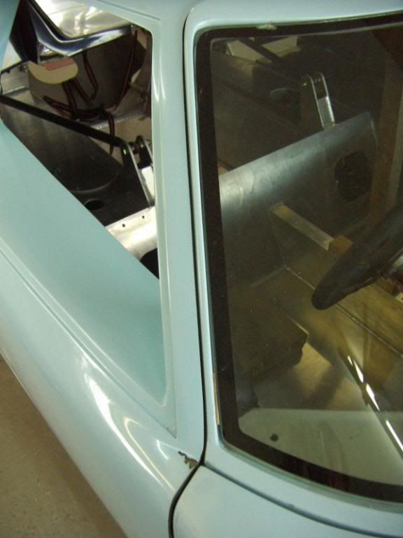
I then decided to put the doors on. I made 4 aluminium backing plates with nutserts in them to make fitting the hinges to the chassis much easier (no spanner behind to hold the nuts). I made 4 horizontal slotted holes in the chassis, with the vertical slots in the hinge this will allow hinge movement to align the doors.

As we all know the standard design uses two bolts to attach each of the hinges (a bolt and nut on the top and another set at the bottom). I found it a little tricky to fit the door on my own like that. So by following some other builds as inspiration I purchased two 1/2" UNF x 10" long grade 8 bolts to replace the standard items. This allows me to run one long bolt down the door hinge. I also purchased different thickness nylon washers to place between the moving hinge elements to get a tight, rattle free fit.

DSCF3723.jpg


The door fitted well but still needs a lot of adjustment to the other panels. I'm reluctant to trim any panels at this time as I have heard people say that they got good preliminary fits without shaving parts. We will see if I am good enough to get that to happen! Reading other build threads on this forum has given me a serious inferiority complex :laugh:

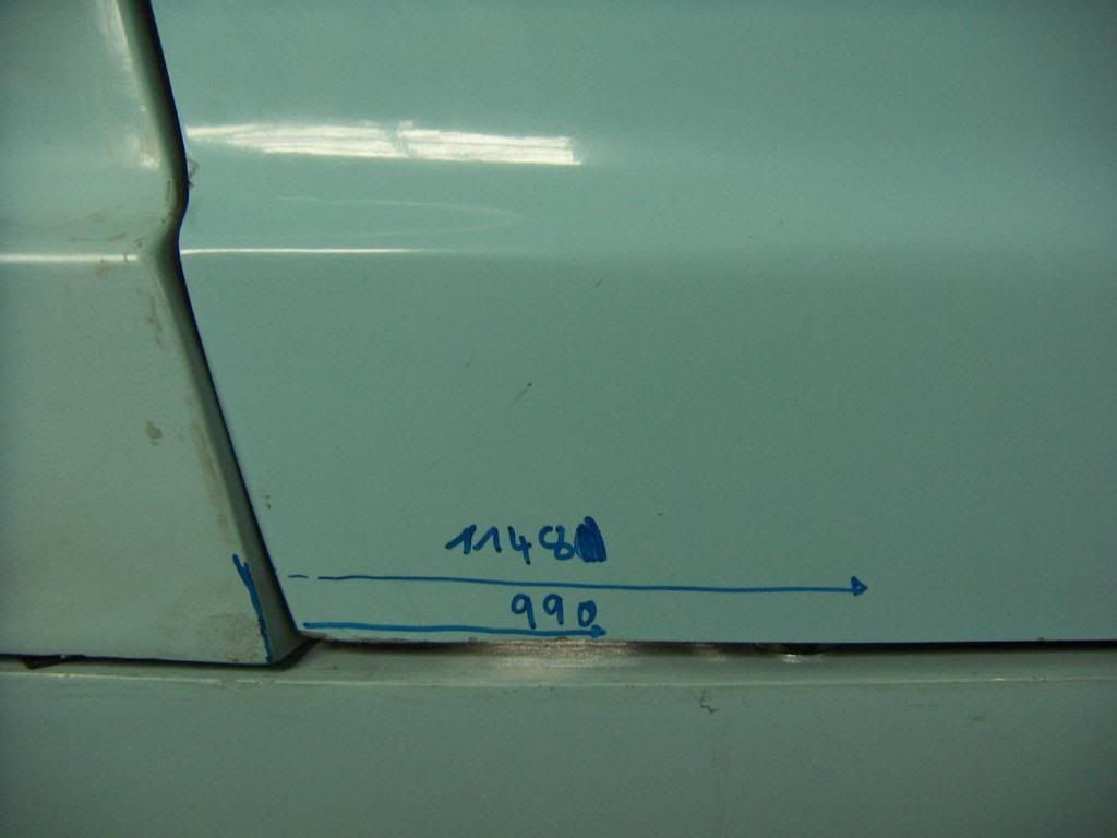
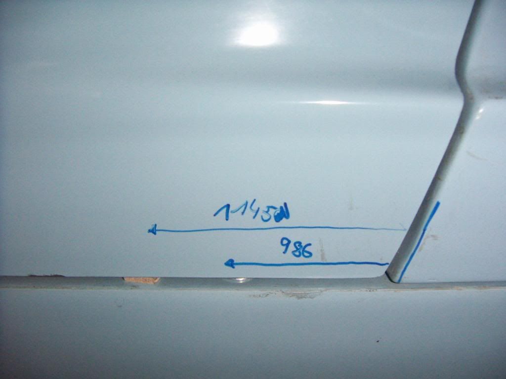
Also not sure about the 66" dimension from rocker to rocker. It looks a little wide for my front clip (I have to stretch the front clip to get the alignment pins to lock in, this may be normal?) and I would need to space my hinges off the chassis by quite a lot (~15mm) to get the front of the door to line up to the rocker panel. Just an observation and I'm not worried as I really need to get everything on before moving parts around for fit.

DSCF3721.jpg

DSCF3722.jpg


DSCF3724.jpg


I may weld the lower nut to the chassis hinge as it will make the fitment and removal of the bolt even easier. I may also weld a tube between the door hinge plates to help alignment of the bolt through the hinge points.

Not sure if that will limit the adjustability of the door though, any comments would be appreciated.
 
Jason,just one caution before you go off and start welding - try these items with a minimal tack weld first.After the doors are aligned and mounted you may want to remove some of these helper devices as you wont be repeatedly assembling / disassembling all these pieces.Also,if you're going to use a seal or some sort of rubber/tape under/around the windshield,you will gain some height there but this seems to be a misalignment with the cowl(spider),not the windshield.Is that correct?Fran would be the ultimate authority on this but I was given to understand that the key is to get the rockers right,then proceed from there. Just my 2c. A.J.
 

Chuck

Supporter
Jason:

You are making good progress. Body alignment is a slow process.

Some thoughts:

1. The front clip did indeed have to be 'stretched' to get it on the pins, so at least start with the specified distance from one rocker panel to the other. The clip will settle into place with time.

2. You are correct in not shaving any fiberglass until you have a good preliminary fit. The only edge that needed shaving on mine to get a decent initial fit was the leading edge of the rear clip. The descrepancy from one side to the other was obvious and once evened out it came together nicely.

3. You will likely need spacers where the hinges secure to the chassis - likely a quarter inch or more on each side. It won't necessarily be the same on both sides.

4. The leading edge of the spider needs to come up a bit where it rests on the chassis. At least an eighth to 3/16 of an inch. Use some small washers initially, but when final assembly is ready, a nice bit of adhesive backed foam provides a nice seal, the needed elevation, easily removable and no gooey mess from silicone sealant.

5. I would defer welding that nut on the bottom of the hinge bracket. Frankly you don't need a nut in that location. The door hinge won't be going anywhere. You can always add it at the end of the build.

The buzz word to keep in mind: patience!

Chuck
 

Randy V

Moderator-Admin
Staff member
Admin
Lifetime Supporter
Hi Jason.... I think you will need to re-do your door hinges... :(

Take a look here on my build site;
http://www.gt-forty.com/GT-Forty/Doors.html#grid

The bolt will need to pass through the door itself rather than in front of it.

Shimming of the hinges - It varies for some reason from car to car. Mine takes a 1/4" shim on the right side and a 1/8" shim on the left...

My car also did not work with the 66" Dimension. It's narrower..
 
Jason

Randy is correct. They way you do it the door will be far too much located towards the rear. The bolt need to pass through the door. Also take a look at chucks built thread or mine.
I think you also need to move your rocker panel backwards quite a bit, to close the gap between front clip and windshield base. You are correct on the 66" spread, this is not where most of us ended up it is more likely 65" to 65,5". Check with your wheels on and turn them in and out, this will give you also an idea how fare you have to move back with the rocker panels.

Chuck has a pretty good short description on how to start the aligning in the exteriour forum,


Thanks
TOM
 
Thanks guys, will re-do the door (only done the LHS:shy:). Did you taper the rockers in at the front or did the spacing differ to the RCR guide along the whole length? I gather you kept them parallel but just checking. Thanks, this answers a lot of questions.
 

Chuck

Supporter
Jason:

My finished dimension was 65 1/2 at the aft side of the base of the dash support ( B pillar) and 66" at the fire wall behind the seats.

But as Tom as pointed out on his build blog, all the body panels need to be set in place and permitted to 'float' until the alignment has been massaged into place, so any attachment of the rockerpanels done now may be strictly temporary
 

Rob

Lifetime Supporter
Jason,
Chucks comments about not permanently mounting at this point is dead on. Fran made a good suggestion the other day for this process, which was to use clear packing tape to tape the rocker down. This will permit the rockers to be moved during this "dialing in" process.

Regarding your hinges, the one thing that wasn't mentioned below is that your hinge plates will need to be flipped when you redo the pin location. Just in case you didn't catch it......

Keep the faith man....this is the toughest part of the build. At times it'll get your head spinning....but you'll get it....:rolleyes2:
 
More Panel Work

First job was to correct the door attachment, the door bolt was supposed to go through the door and the mounting bracket flipped:idea:
Correction did not take long. Next job was to ensure both rocker panels were as far rearward as possible.
RH & LH shown below.

DSCF3755.jpg


DSCF3756.jpg


I then attached the rear clip. The LH side of the clip (not shown) sits level on the rocker panel, the RH kicks up a little at the front as shown below. I will also need to look at moving the rear of the spider back and adjusting the doors rearward a bit to close the gap to the rear clip.

DSCF3787.jpg


However even after moving the door a little further back I expect the front clip position will still be an issue. Front clip bobbin movement suggestions from RCR Australia have not been able to correct the issue. It looks like the front clip is warped (bent upward in an ark along its trailing edge), it actually has small kinks in the trailing edge of the front clip so I'm pretty sure its bent, possibly during shipment as there are large flat spots on the top of each front fender where it was resting against other parts. I have a battery on the top of the clip to bend it down as it sits very high against the spider. It looks like it is slowly getting a lower set and lining up with the front of the spider a little better.

The doors also seem to have some added material which may be affecting the fit of the front clip, I'm not sure if this is normal for RCR kits, maybe someone else has seen this as well? I do not want to shave any fiberglass yet though so I will move things around a little more and see what I can do. Others get fits without cutting anything, but here I'm not sure.

DSCF3789.jpg


I did have to chop a bit out of the lower part of the rear clip to clear the transaxle. I will glass a bump in here so that it is not that obvious/ugly. The temporary metal work inside stabilises the rear alloy panel as it was cut in half to clear the transaxle. I will machine an alloy structure here once I work out the exhaust system.

DSCF3784.jpg


DSCF3792.jpg


Overall the rear clip looks like it will fit fairly well, still not sure about the front one though. Lots of work to go yet on this body adjusting, all part of the fun.

DSCF3797.jpg


Also attached the number plate for fun. It will be a while and a lot of outstanding compliance documentation before it can wear it legally!

DSCF3801.jpg


DSCF3799.jpg
 
Test for High Definition video YouTube link. Trying to get the HD (720P) video to come through directly on this site failed. Gave up getting HD by default and added a link to my videos page on my GT40 build site. HD video of my car looks great though.

Just need to get more done on the car so that all can hear a supercharged 6.0 lt GT40 engine come alive in 256 Kbps AAC audio!

Link below.

http://claw.com.au/gt40_videos.html
 
Last edited:
Jason

try the following.
- set position of front clip without bobbins
- if that is better check if the bobbins are not locking the movement of the front clip.
- the aluminum sliding bracket is usually a little to wide for the moulded opening in the inner liner. So shape the outside of the aluminum to provide a nice fit into the inner panel. Than mount it and try to slide in the bobbin, you could experience that at some point it is a little tight and the bobbin is not sliding in nicely. See where it locks and file the aluminum accordingly to allow the bobbin to slide in nicely.
- the width of the bobbins mounted on the front frame is maybe a little to wide, which at the end doesn´t allow you to move the front clip a little from left to right ( which has an effect on how it fits along the spider base and how it twists). Find a good position of the front clip without the bobbins, measure the distance from moutning surface of them to the inner liner and shorten them to a total lenght 5-8mm shorter than this dimension. They are not nec. the same lenght both sides.
- reinstall them in a way that the effect of the excentric adjustments are used backwards towards the chassis ( not towards the front) thus allowing you to move the front clip further back (one can have the same height adjustment by turning the bobbin to the front or to the back except for the highest position, the back position is providing more adjustability for moving the front clip backwards
-do not fasten the bobbins to tight, you should be able now to grab them ( with the clip mounted) with a small pair of grip pliers and rotate them. just play around on one side and observe what the front clip is doing. Rotating them let the one or the other top rear corner of the clip point out or come in. Try to get a feeling for that movements.
- mount your front clip to rocker panel location pins in a way that asures the perfect line up of the rocker and clip wheel well line
- if you got a good location from left to right, rotate both bobbins in the same direction to get a nice and even gap where the front clip sits on the rocker panel ( like here)
PICT1514.jpg

-All the time by doing this have your doors out, your rocker panels loose , your spider b-pillar loose and the rear clip of ;
now just play with the spider base and front clip position. you could now move your front clip as far back as possible to have the correct rocker panel location. Usually the right hand side rocker panel is closer to the chassis as the left hand side one ( means a little further back)
-If you have found a position where the spider base is located on the chassis with even dimensions of the chassis standing over on each side (+- 2 mm) and the front clip corners align nicely with the spider base corners like on this picture
PICT1512.jpg

fix your front spider base position to achieve a nice even gap to the front clip ( dont bother about height differences from base to clip now you can adjust this later on. ( see pic)
PICT1513.jpg


-now set your doors to fit the front clip and the a-pillar of the spider
PICT1511.jpg

next step would be to set your b-pillar position according the rear door gap
PICT1515.jpg

last thing is to postion the rear clip. you may experience a not even gap between spider and rear clip and rear clip and rocker panels. for the first one it located the clip in a way that the dimension from the spider to the rear end of the clip ( spoiler) is identical on both sides.
gap differences to the rocker panel can be adjusted with the rear clip height on one or the other corner ( watch that the spoiler is still leveled afterwards.) Also check your left to right positioning ( same dimension from the vertical tireline to the wheelwell)
CHeck this pic: THats the method is used to find the postion of the rear clip. If you have it fixed mounted on the hinges you can not be sure if they put a missalignementforce to the clip. i have had a 3mm wide wooden pieces between the rocker panel and the clip base to adjust the gap there and had the rear end of the clip supported by long wooden 2x1" bars. You are always able to put some material underneath this bars or shorten them to adjust your height and level. THis way the rear clip is free floating untill it fits.
PICT1559.jpg

after finding the correct position mount your hinges with the correct number of washers nice and straight to avoid preload.

Do spider fitment without the firewall ( it may lock you at some point) you can cut it to fit later on.

One last thing. SDOn´t bother about your door tops standing under the spider level, The correct weatherstripping will preload them and they fit just perfect. The Mcmaster carr weatherstripping in the build manual is perfect.

Hope that this is understandable ( limit of my english) and helps

TOM
 
Last edited:
Chuck
as nice as yours ! And i achieved the same on Simons car


BTW used the same method to keep the doorhandle flush
TOM
 
Last edited:

Fran Hall RCR

GT40s Sponsor
Show off....!!!!!

Here is the third RCR Australia that Craig has mounted, ready to send to a customer...still in gelcoat
 

Attachments

  • rcr aus red car (Small).jpg
    rcr aus red car (Small).jpg
    51.7 KB · Views: 834
Thanks Tom, your commitment to assisting others is astounding and your English fine!

I will follow your recommendations to the letter during the Christmas break. To think your setup was accomplished without shaving any panels is amazing. I feel I will definitely have to trim at least my RH door as it has some different "additional part lines" that I have not seen in any other door photos.

By the way if any other Australian RCR 40 owners are out there it would be great to make contact, send me a PM, email etc.

Got a new video up, amazing how easy it is to create a video with the software available today! Try it full screen, the YouTube HD option is great. I hope to use this to better explain my build progress in the future.


Click here: GT40supercharged.com


GT40-Introduction-Video-1.jpg
 
Jason

you´re very welcome
Here are my dimensions from the right hand door ( upper dimension is till wheel weel, lower is the door opening, always measured from the edge of the spider b pillar)
PICT1585.jpg


left hand side
PICT1586.jpg


Also if you go to my photobucket account, under body alignment, there are tons of pictures, may be they are of some help.

schwabtom - Photobucket - Video and Image Hosting

If you go to my website, there are my contact datas, call me if you need further info´s and support

TOM
 
A comment made long ago by Ray Christopher about felt tip markers being used on fiberglass. DON'T- they tend to bleed back thru paint. Just thought I would mention this as your markings look like felt pen. If it is be sure and get it totally removed before paint!
 
Better Gap Alignment - Two Questions.....

Thanks to suggestions on the GT40s forum I first aligned the front clip with the spider (bobbins, roll cage and firewall removed). Much better!

Aligned the front clip corners well although the clip is still warped in the middle due to shipping and will need some glass work to pull it down level with the base of the windscreen. The battery has sat on it for a month and its not enough.

1DSCF3804.jpg


1DSCF3808.jpg


The spider's B pillars were adjusted into position (measurements from EGLITOM in the forums achieved, thanks). The doors still need to be better aligned to close without moving the spider.

1DSCF3802.jpg


1DSCF3805.jpg


1DSCF3803.jpg


1DSCF3806.jpg


One concern is the fact that the front clip appears shifted to the right by ~20mm (see below). The front clip sits over the wheels evenly and the bobbin gaps are fairly even. Is this simply one of the GT40 body peculiarities, the front opening is not centered on the clip, or should I look for the cause? Its just that the panels are sitting well and any attempt to move it over twists the spider etc.

The fitment of the AC condenser will hide it anyway but just would like to know if this has occurred to anyone else?

1DSCF3812.jpg


Also, the distance from the top of the radiator to the bottom glass surface of the front clip is 75mm, is this too high? It makes the front clip level with the rockers but just checking.

1DSCF3813.jpg
 

Randy V

Moderator-Admin
Staff member
Admin
Lifetime Supporter
Jason - I had similar fitment issues as you only the front clip is actually shifted to the left. I adjusted much of it out of the front and and mine is now off set by maybe 5/16-3/8 of an inch to the left. See my build site for more details and maybe my build thread (somewhere in here - I never go to it any longer).. Remember that these bodies are shorter on the left side than the right by various degrees depending upon how the doors and rear clip were cut originally. I have mine now so the left side is shorter than the right side by only about 5/8" as I recall..

Dealing with the offset of the front clip / bobbins was a bit of a chore. I eventually cut shims to go betwen the bobbin on the left side and the sidewall of the chassis it was bolted to. This allowed the front clip to float a little more free rather than being bound up by the bobbin trying to pull the clip back towards center.

Also - Fiberglass warps. I used a heat-gun - warming the fiberglass to 160-180f and pulling and clamping it into position. Once cool, the fiberglass will retain it's shape very well. I had to to this to my front clip as well since the right side "Foot" (part that sits on the sill) was too far to the inside by about 1".
 
Back
Top