Jason's Coyote Powered RCR40 Downunder

Hi Jason

looks good to me, as a basic setting. So now try to move things around just a little at the time. By doing so you will gain even more understanding how this body works.
Front clip:
Here is a picture of mine.
PICT1528.jpg


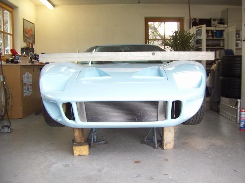
Fairly even gaps, although also a little of to the right ( or left if you see it from the drivers perspective).
Check your front aluminum sidewalls first, if they are runing true with the chassis. If not align them first and check where the clip opening is than in relation to the radiatior.
Than turn your windscreen spiderbase a little clockwise. It probably don´t need much there to have a nice effect on the front. Also view along both sides to check if the lines are flowing nicely. To have it adjusted to + - 5 mm would be perfect. This something of the specifities of this cars, especially of the ones they are so close copies of an orginal one.

The height could possibly be a little lower . 1 or 2mm there could give you a lot more in the front, but also can be grinded on the contact edge towards the rocker panel to have a nice even gap there later on.

Be carefull with the heat gun. I would use a Halogen spot ( 500W) don´t put it to close, Heat just as much to the poitn you can barely touch it and use little clamping forcese over time. Glassfiber is not termoformable in the usual sense, but i can be moved with heat and time.

THanks and merry christmas ( i´m still available also on the phone)
TOM

Give yourself a few more days playing around with it, before fixing.
 
Last edited:
I have continued to work on the body panel fitments with limited success.

1DSCF3829.jpg


1DSCF3833.jpg


1DSCF3834.jpg


1DSCF3831.jpg


I have achieved the same door opening spacings as others (Eglitom in particular, thanks) but to line up the front corners of the spider and the rear legs without affecting the alignment to the rear clip is not possible. I need to induce some twist into the spider to get the rear to line up, this then throws off the front corners of the spider. They must line up with the doors and front clip corners. If there is one part of the body that one cannot flex it is the leading edge of the rear clip (it's stiff as hell), so the trailing edge of the spider must conform to the leading edge of the rear clip.

So I feel the only option is to fix the rear of the spider to the rear firewall to both make it airtight and hold it to line up with the rear clip position (as shown in the images above). Then I can align the front of the spider with the front clip and doors without affecting the rear. A couple of questions:

1) Has anyone made fiberglass features on the spider in the area shown below to fasten it to the firewall? If so any recommendations before I start?

1DSCF3837.jpg


2) Is the rear window frame always obstructed by the spider? I want to fit glass so I will need to trim more away from the spider's inner roof.

1DSCF3835.jpg


Thanks.
 

Randy V

Moderator-Admin
Staff member
Admin
Lifetime Supporter
I need to induce some twist into the spider to get the rear to line up, this then throws off the front corners of the spider. They must line up with the doors and front clip corners. If there is one part of the body that one cannot flex it is the leading edge of the rear clip (it's stiff as hell), so the trailing edge of the spider must conform to the leading edge of the rear clip.

First off - as I've made sure to note on my website - These bodies are like snowflakes - I don't think that there are any two of them identical to each other. This is not in respect to the mold itself, but in how the body has cured since it was removed from the mold and who trimmed it and / or bonded the inner and outer pieces together. Remember that these cars were designed and built in the 60's and the tolerances on body fitment were fine for a racecar but not up to the rather loose standards of a road-going car of the day..

All that said -
I had similar challenges with the body. The Spider was of particular concern since mine was warped, probably due to my having stored the car inside a hot trailer for 6 months prior to even working on it and the spider may not have been properly supported.
I needed to do some twisting, lifting, turning of the spider to get all the pieces to come together. This was an exasperating exercise that took me weeks of my spare time to finally bring together into something that worked.
I could have saved myself a LOT of effort had I just made this model ahead of time (this is the first time I've shared it I believe). Made from an old Tissue Box, I cut out the basic shape/structure of the spider. I could lift and twist this and see immediately what the effect was on all the other sides and corners - rather than doing it with the real spider which would take a long time.

IMG_1794.jpg


IMG_1796.jpg


..
..

I opted to take out much of the left side's "shortness" over the right side by trimming the rear clip at the angle needed to make it fit "properly" (by my terms).

This would entail twisting the spider slightly anti-clockwise as viewed from above.
As you may recall from other posts - I had to deal with a "Z" in the spider as well. BTW, some of the Z in the spider was caused by the rear bulkhead which was interfering with the shape of the spider's rear opening. Once I removed the bulkhead, I could more properly address the shape of the spider and how it related to the opening of the rear clip.
::
::
After having dialed in virtually the entire body no less than a dozen times, I finally found one setting of the spider and rear clip that worked well from the doors on back and the front clip fit okay as well (although it had some other issues to address because it too was warped).
::
::
Here is what I ended up with - the only real "problem" area to deal with - this is the right front corner to the spider interface. Note that the doors fit nearly perfectly at this point. The spider is sitting flat on the front of the tub and elevated ~1/8" as prescribed by RCR at the rear feet of the spider.
:
Looks "ok" from here
IMG_1847.jpg


IMG_1851.jpg

::
::
But then - looking at it from the front - I saw this;
IMG_1849.jpg


IMG_1850.jpg


IMG_1852.jpg

::
::
These are the measurements that prevent these various points from being flush with the right side door;

IMG_1858.jpg

::
::
Finally - This is the part of the rear clip that is in error and will need to be cut apart and re-glassed to address most of the interface issues with the door;
IMG_1859.jpg


You are right in that this is a very heavy part of the car to work on. I though about trying to break he bond between the inner and outer panel, but I fear that this would lead me to more trouble. I will make a vertical cut in the inner panel, remove some material and re-glass the area with additional support on the inside of the structure.

All in all - it's a small price to pay for a body that now fits decently.

I hope this is of either some help - or encouragement to you and anyone else that finds this thread in search of answers..


Note: The alignment pin at the front of the rear clip had to be removed in order to get proper alignment of the rear clip and to not "force" it to an un-natural shape. The metal you see under the front of the rear clip's foot is washers used for spacing. Forcing it to fit over the pins as originally installed did remove much of the interface problems at the RF corner of the clip, but it introduced a host of other problems elsewhere.
 
Last edited:
Jason

there is usually a lip for fastening the spider to the firewall ( it is on the inner liner) . Did you cut it of ?

TOM
 
Jason

On the pic onby you can clearly see the original edge of the inner spider liner , which is meant to fix it to the firewall. it extends over the whole width of the spider. it mounts on the front of the firewall. Therefore the firewall window has to be mounted on the backside of the firewall(not on the front like you show it) and thus will no create any clearance issues.
PICT2839.jpg

To mount the edge one can use the very same bolts which are also holding the window frame.
PICT2861.jpg

TOM
 
Thanks guys a heap! I feel I owe you both an assembly consultation fee, I gather one in Euros and the other USD!

Love the tissue box, great idea. Sorry to hear someone else has spent weeks on the spider etc. My Xmas break has been absorbed by that particular piece of fiberglass.

I have exactly the same issue on the RHS of the rear clip after best positioning of the rear of the spider. ! It has the same misalignment.

1DSCF3839.jpg


I also considered separating the inner and outer in this area, it sits too high near the air inlet (the front locating pin is not yet installed and will pull it in). I installed the rear RHS RCR latch to try to pull it down slightly but it will still need some work. I must get better clips too, anyone recommend some good replica clips?

The rear window surround was installed in this fashion from RCR, I could not find anything on their brief build manual to show otherwise. Eglitom are you saying the surround should be fitted to the engine side of the firewall? If so I will flip it to the rear of the firewall.

I cut the damed flap off as it fouled! May need to glass it back on!

Yes and Yes you should:thumbsup:

Over all my body alignement took me 40-50h the first time. Then i made my trip across the US and after seeing a lot if different RCR´s and discussing with the owners i decided to redo my body alignement from scratch. Took me one day to disassemble and put it together again ito the result you can see on my build log. Now as i found all the correct positions i can take each part on and off within minutes and it fits perfectly again.

TOM
 
Last edited:
Re: Jason’s Australian Supercharged RCR40 Build - Spider Position

I fear that my whole body is too far back on the chassis. I have pushed the rockers to the rear (as reccomended) to get front wheel clearance etc. but I think I have gone too far. The lower edge of my window seems further back compared to other photos on the forum.

Can another RCR owner tell me how far back the leading face on the spider B pillar (Marked A!) is from the front edge of the tank (Marked B)?

333DSCF4033.jpg


33DSCF4038.jpg


My dimension is 1,093mm or 43". Is this too far?
 
Further Body Alignment Work

Again a lot of help from the GT40s forum has given me some good progress on the body alignment.
The front clip was moved further forward on the chassis. The bobbin positions (not sure if I will keep this attachment system) are shown below. I did need to work on the front clip quite a bit to get the bobbins to slide nicely in the groves.

5DSCF4070.jpg


5DSCF4086.jpg


The rocker panels are adjusted to be as far back as they can go (used the 52mm-55mm measurement from the rear of the rocker to the chassis from RCR Australia).

The spider was positioned (further forward this time) and the doors aligned. Its all starting to look a lot better now, however I have had to remove 10mm-15mm of length from the front of the doors to get the opening to what others list on the GT40's forum have and for the body to fit within the rocker length. I'm sure the door trimming was "different" on my doors. The result below is getting better.

5DSCF4073.jpg


As can be seen on the door before trimming (both LH & RH were like this) there appeared to be added/extra material on the doors. No-one has been able to tell me what this was but it definitely was screwing up the alignments of the clip last time.

5DSCF3789.jpg


So the rear clip, spider, front clip and doors are getting closer. I also spaced up the LH side rocker by 3-4mm as the chassis sat lower than the RHS and this really helped to close gaps under the LH door etc.

I still need to address the alignment of the RH side of the rear clip as it still sits a little high and out. I will fit my replica Hartwell latches (thanks MDA) and see if I can pull it down into position.

5DSCF4081.jpg


5DSCF4072.jpg


Then I will adjust the doors. However the RCR supplied seals have a 7/16" bulb which is too small for my car and does not seal against most of the door so I have unfortunately had to order some replacement 5/8"seal from from Mc Master-Carr USA (Part# 1120A431 EDGE-GRIP RUBBER SEAL, BULB OPPOSITE GRABBER, 1/4" EDGE, 5/8" BULB WIDTH) as I see others on the GT40's forum have done. When this arrives I will dial in the doors as its a waste of time unless the seals are in position.
 
Last edited:
Looking good Jason. Well done mate.

Yeah, it's normal to trim off the extra material on the front edge of the doors. We do that on all the RCR-40 kits we deliver.

With the bobbins we actually turn the flange down a little for that side that binds a little on the front clip.

Looks like you had a very productive Easter. :)
 

Brian Hamilton

I'm on the verge of touching myself inappropriatel
Hey Jason, I was just looking at your build page. I had a question for you though, do you think you can turn the supercharger around so it's backwards from it's original setup? This way you can route your intake air charge wherever you'd like it and the belts all line up correctly and drive the blower directly as opposed to that jack-shaft drive. Just an option, check to see if the blower will bolt up correctly backwards.

Laters,

Brian
 

Randy V

Moderator-Admin
Staff member
Admin
Lifetime Supporter
Further Body Alignment Work
5DSCF3789.jpg

Jason - I had a problem like this with my front clip. The "foot" of the clip was disposed to fitting well inward of where it needed to be. If forced to fit over the alignment pin, it would torque the whole clip into an unnatural position that did not work well. After working through all the other positions with the clip, spider, rear clip, doors, etc - I was finally resigned to heating and re-forming the foot area just below the crown or peak of the front fender. Once I did that - everything seemed to fall into place.

Also - I too needed to do a bit of work on the bobbins. Cutting down the right side Bobbin about 3/16" as I recall and spacing the left one out about the same about.
 
Thanks for the heating tip big foot, I will look at that for the RH rear clip foot.

Regarding the supercharger, I have been working on a custom lay-shaft drive concept to work with the supercharger that will position the inlet to the supercharger facing the rear of the car. Its a special setup that will clear the firewall, not an easy task!
 
Jason

The heat trick won´t work on the rear clip foot, because you would have the inner liner the outer liner and the glue inbetween. This is to strong in itself to move it. The only way would be to separate inner and outer liner and glue it back together in the new desired position.
TOM
 
Front Clip Hinge Changes

Revised Front Hinge System

As I tend to work on the car on my own I needed to revise the standard RCR front hinge system as it was too easy to drop the front clip on its nose when opening it. I also wanted to make it easy to release quickly which the original system had. I used the Jergen's quick release pins (thanks Eglitom) at the front as well.

CAD1.jpg


Using heim joints allowed adjustment up and down and the main bracket allows fore aft adjustment.

DSCF4169.JPG


DSCF4167.JPG


Brackets will be glassed in properly when I'm convinced of their position. Front clip is tilting perfectly and not deforming even before I add some additional glass ribs to the clip area.

DSCF4141.JPG
 
Back
Top