Jason's Coyote Powered RCR40 Downunder

Thanks for that Trevor, that is good news on the seats. I'm in VIC. When you say a full harness is permitted is this in lieu of a recliner belt?

What seats do you have in your 40?
 
Last edited:
Jason,

Thank you for solving my dash/rollcage fitting problems. An elegant arrangement.

Re seat ADR's - I believe these only apply to adjusters and head restraints. None actually apply to the seats themselves, meaning the construction material, covering and (non moveable) mounting method is signed off as acceptable by your engineer.

Your attention to detail is stunning, and the bar you have set has me questioning every rivet I am installing:bow:

Clive
 
Thanks Clive but way to kind. With these forums I find someone has always done a better job at most things due to better skills, more time or money! I'm moving onto seats and pedals next and dont know where to start! More forum trawling :sad:
 

Randy V

Moderator-Admin
Staff member
Admin
Lifetime Supporter
Exceptionally nice work on the dash and door boxes. I am fitting the RCR door boxes now and am wrestling with the notion of making them just fit flat to the door or recessed as you've done. Either way will require the introduction of filler material to the door itself.

The dash - well - you've done what we all should do.. I've got the ends cut off of mine as well to fit between the A-Pillar bars of the roll-cage. I've not yet decided how to secure the ends. My dash does not fit well underneath the front of the spider but will if forced. I think I must have let it warp while it was in storage in my hot trailer over the summer.
Great job all in all!!
 

Trevor Booth

Lifetime Supporter
Supporter
Jason

ADR 3/03 is applicable to seats and seat anchorages and covers the strength of the seat and its anchorages. Anchorages must suppoport 20x mass of seat in fore and aft direction. There is also a requirement for the strenght of the seat back. If the seat is fully supported by the body and is not on adjustable tracks the seat in itself need not be "ADR approved" so no seat back test is required, however the seat anchorages need to comply. This can be done by simple calculation.
Head restraint is covered by ADR 22, however, 3/03 now includes a test for head restraint.
Your Engineer can assess which way to go for head restraint compliance. In NSW it is a requirement to have some clearance between head restraint and body (100mm ~) to allow some displacement to absorb energy.

full harness belts without ELR are acceptable under ADR 5/05, the belt must comply to ADR4/04. this does not mean that you can use FIA or SFI approved belts unless they also comply to ADR4/04 or ECE R 16

You should be consulting with a VASS Engineer NOW as what you think is ok may not be.

The seats I used I made. The back is formed from alum sheet (shown "in progress" in photo) the base is pirelli webbing
 

Attachments

  • P1010534.jpg
    P1010534.jpg
    20 KB · Views: 769
Thanks Trevor. Anyone know of a good practical certification engineer in Victoria? I don't have one yet. The two I have had here in the past freaked out at the custom parts, for example non OE suspension arms. I may post this question in another section of this forum as I do need to get someone on board. Thanks.
 
Last edited:
Jason, just me know which engineer you want to work with and I will pass on our certification and testing documentation directly to him. Not all of it will be applicable as the Australian spec RCR-40's differ in a number of areas to how your kit was supplied.

Your suspension will be slightly different to ours, but our suspension documentation will still be applicable and should satisfy your engineer.

You will also need seat belt mount testing/certification results due to the aluminium chassis. Even if your engineer does think you will require them, you will. I sent you the details on our mounts a while back, so if you fit the same mounts, you can also use our seat belt mount documentation.
 
Last edited:
I would also recommend fitted retractable lap sash belts. In my opinion they are much more suitable for street use. For track days you can fit much safer harnesses than those ADR/ECE compliant harnesses.

Trevor's compliance information on the seats, seat belts etc is spot on as usual.
 
Thanks for the assistance and recommendations Craig. Much appreciated.

If anyone can PM me any Victorian compliance engineer names or contacts that they have had a good experience with it would be appreciated.
 
Jason,

The clubman builders of Vic should be able to point you in the right direction re engineers. Virtually every clubbie has home made/fabricated suspension arms, and they are not usually any problem for rego. I have built two, using chrome moly tubing, and no questions asked by the engineer or rego authorities. My 40 is similarly equipped, with all these builds using 100% 'Rose' joints.

Can I suggest a search of Oz-clubbies.com for Vic engineers could be worthwhile.
 
Possibly a stupid question! Does everyone get their steering wheel in the center of their seating location or do they deal with an offset to the center of the car?

Also do most GT40's have a 14" diameter steering wheel? I think that is what a Superformance 40 has.
 
Last edited:
The rhd drive RCR allows you to exactly center the steering wheel over the seat position. THe steering axle also runs parallel to the longitudenal axle of the car. So the steering wheel is also perpendicular to the drivers seating axle.
Of course the seat is postioned to the very left. I also modified the steering column, Got rid of the second crossjoint. Runed it straight from the first joint up to my desired position. Did a cut out on the chassis crossmember to get the space to do this. reinforced it afterwards with a aluminium angle stock.

Depending on your leg length the pedals can be set also centered to the seat position.

TOM
 
Last edited:
More Work on the Dashboard

So after getting an RF dash and working on the top it was time to look into the gauge and column area. I tacked a temporary column in position and as can be seen in the image the centre of the RCR driving position is different to the RF (possibly due to the RCR having a larger drivers side area than the passenger side), time to cut and shut the dash.

dashlineup.jpg


After much cutting and glassing it was time to cut the holes for the gauges.

cutshutdash.jpg


Some may notice I have added an extra gauge on the left, needed one extra. A quick trial fit of the gauges and all was looking OK. I purchased some custom manufactured gauges and sender units from the USA that are all digital and have some custom additions like high beam indicators etc. These were also tricky to fit due to the way they attach with a small threaded ring on the rear but the job was done. Here you can also see that I have inverted the fibreglass lip under the dash to give a little more leg room.

DSCF5308.jpg


trialgaugefit.jpg


Next job was to make the alloy plates under the gauges and prime up the dash. cutting, bending and rolling the alloy plates was a PITA! I had this vision of a pair or perfectly shaped plates when I started and I was going to be dammed if this is not what I finished with! After many hours of metal rolling (I have one of those 3 in 1 metal bender, guillotine and roller units) I did get what I want. Its funny, only people who have made these will possibly know how the shape is a little tricky to get right, especially the curve under the dash.

DSCF5312.jpg


DSCF5334.jpg


I also inserted some AC vents into the dash. The plates may be black but they are polished to check shape and bend continuity. I also wanted the top edge of the dash to be straight (some have a dip down in them that looks like they melted down) this took some work.

DSCF5322.jpg


DSCF5328.jpg


DSCF5330.jpg


Job done on the plates time to look at the steering column.
 
Last edited:
Thanks for the comments guys. Pantera1889 these are great gauges, I purchased a few years back from the manufacturer, they do appear to be very well thought out and customisable and having total freedom in face design was good too.
 
Time to Work Out the Steering Column

The problem here is the things I want!

1) ADR compliant column (a column from a current production Australian vehicle)

2) A fully adjustable column (reach and rake). Mainly due to the fact that building this car with a driving position that is less than ideal would bug me and I don't yet know what a good driving position is!

3) I need a lot of foot well room (size 12 feet) and these columns can run low under the dash causing foot clearance issues, so I want a very compact installation

So the fun begins.

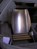
I have chosen to use a column from the current model Australian Ford Falcon/Territory. Now some people have said it will not fit so now I had to use it! What you can see in the picture is a few columns I was able to obtain (I have 3 as I was sure I would destroy a few along the way).

steeringcolumn.jpg


Below is one of the many OE sheet metal mounts and columns I have (this rusted one is for trial use only). By using this I can ensure that the shear away plastic mounts on the column are fitted to a fully compliant OE structure and the column will behave in an OE manner in the unfortunate event of a collision by shearing off the mounts. Very important for ADR compliance.

DSCF5154.jpg


One of the first things I noticed when planning the rack fitment was that if I was to rotated the steering rack about the centre of the rack I could push the column up higher in the foot well without changing the RCR steering geometry. I purchased a set of pedals from Jim Cowden (really are terrific pedals, not sure if I will use the accelerator yet) and below is the result if I leave the rack input shaft horizontal. I cannot drive a car like this!

DSCF5240.jpg


So I began planning to rotate the entire steering rack and things looked a lot better. RCR had spacers fitted and this is a godsend. I can use this space for rotation of the rack. I achieved 22 degrees of rotation in mock-up (this angle is important and I will detail in another post why) and the shaft will be pushed high up along the top panel of the foot well. Now to rotate the steering rack permanently.

DSCF5258.jpg


CAD to the rescue (I have cannot start cutting metal without a plan and have to design everything first!) and the following were machined up from 6061T6 alloy and fitted.

CADsteeringrack.jpg


Ribbing was added while I milled them for additional strength.

DSCF5437.jpg


Both brackets have exactly the same angle.

DSCF5438.jpg


Drawings were created and plotted to ensure the rack position was kept correct when cutting the chassis. Mark 1,000 times and cut once for me!

DSCF5444.jpg


When assembled the wedge mounts do not look to out of place.

DSCF5452.jpg


The brackets achieved the angle I was looking for and pushed the column high up in the foot well. The non nyloc nuts are for temporary installation only.

DSCF5458.jpg


Next job is mounting the column.
 
Back
Top