Jason's Coyote Powered RCR40 Downunder

Hi Jason,

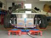
From your image, the front suspension arms are not correct in geometry.

I am not sure that your front ride height is actually at 4.5". But if it is, you have put the roll center at or below ground level.

This is very bad for many reasons, but namely because the car will try to jack the nose up in roll or bump.

The lower arms should be level or inner mounts slightly angled upwards to get the roll center above ground.

Exactly where the roll center should be in height is a sublect for a loooong thread, and it is not an easy thing to know. The main point is that it should never be at or below ground level.

I made a cheesy image from yours to point out the geometry, the yellow circle is the roll center. As further example, I include a diagram of the front Ferrari F50 suspension for comparison.

Hope it helps-
Cheers
Eric
 

Attachments

  • DSCF3507.jpg
    DSCF3507.jpg
    50.7 KB · Views: 2,260
  • f50Front.gif
    f50Front.gif
    14.2 KB · Views: 2,124
Fran, is the top w/bone outer ball joint change [#38 ] made by Jason ( & Big Foot ) OK , dont 'look' right to me if the a/arm is not threaded & that is a sleeve nut for easy camber adjustment.

Eric, Is that an F50 dwg, interesting that the scrub radius is very close if not at zero.
 
Jac Mac, that top ball joint connection to the A arm is fully threaded.

Jason, if there is enough thread it would be beneficial to fit a nyloc nut instead of those 2 x nuts locked against each other on that top ball joint. That's how the Aussie RCR-40's are delivered.

I'll see if I can get a photo of John's RCR-40 for you Jason. I will also measure the front ride height & tyre diameter. All Aussie delivered RCR cars are being setup this way. Your front ride height is on the low side in my opinion.

Looking good mate.
 

Randy V

Moderator-Admin
Staff member
Admin
Lifetime Supporter
Craig / Jac - I just put the second nut up against the first for a convenient place to park it. I plan on replacing both with a hardened nyloc nut and washer.

Craig - Are you doing the same on those cars you are assembling?
 
Thanks guys, I will replace the nuts on the upper ball joint with a nyloc. Also Eric & Big-Foot, thanks a lot for your time, appreciate the guidance.

Building Ramps and Raising the suspension Height

After comments that the car was too low I have obviously decided to raise it. To get an actual check I had to get it off the lift. The easiest way to do this lots of times was to weld up some ramps. They will be used when the car is finished to park over the lift as I have nowhere to store it! It may make it easier for me to get out of in my old age as well!

DSCF3617.jpg
DSCF3621.jpg


With that done and the car on the ground I measured the previously set clearance. It was way too low. After a bit of adjusting I settled at below:

FRONT
Ground Clearance: 115mm (4.5") (70mm to L) , Camber: LH&RH = -1.8º, Castor: LH 6.1º & RH = 6.2º, LH&RH Toe-Out = ~ 1.5mm, Lower Arm Angle LH 3.5º & RH 3.3º

REAR
Ground Clearance: 130mm (5.1") (85mm to L) , Camber: LH&RH = -1.0º, Castor: LH&RH = 6.0º, LH&RH Toe-In = ~ 1.5mm, Lower Arm Angle LH 5º & RH 6º

Castor is a little high and a few other issues but it should be close enough for the body fitment. Basically the car now looks like below:

DSCF3632.jpg
DSCF3623.jpg


After these photos I dropped the right side of the radiator and front alloy structure to make it level with the rest of the car.

Next job is to brace the rear panel temporarily where it was cut in half to clear the gearbox. This will permit the rear clip to be mounted.
 

Rob

Lifetime Supporter
Looking good Jason. Excellent idea on the ramps. In addition to aiding with Ingress/Egress, working on the car should be a little more comfortable. These darn things are so low, don't know about you, but it kills my back to work on em....

Ride height looks better.

Glad closed the post with mentioning that you leveled off the rad/front structure.... I was debating if I should be nit-picky and mention it or not.;)
 
Steering Problem: Jason’s Australian Supercharged RCR40 Build

Noticed my car has far more LH steering lock than the RH. I cannot adjust it out with the rod ends alone. Has anyone seen this before? Remember mine is a RHD car. I checked the steering rods that screw into the rack to ensure I had not put them in the wrong side but they were the same length so no fix there.

Anyone have any ideas as moving the whole rack over would be crazy, so it would leave me with the only other option to make uneven length custom rods for the rack. I'm sure this is not needed and I must be doing something wrong?

Thanks for the previous info as well guys.
 
Jason
Checked on mine ( als RHD):
1 3/4 to the left ; 1 3/5 to the right , so almost the same.

are the steering rack ends ( the point where the steerring rods connect to) centered when the wheels are straight ? If so the tothgear is not centered on the drive rack. Also if this is the case the only thing you should do is moving the rack. Changing the rod lenght will make them assimetrical and different from one side to the other, resulting in different bump steer results on each side.
How much is the difference anyway ? it will just be important for turning the car and parking !
TOM
 

Fran Hall RCR

GT40s Sponsor
Some RHD racks were shipped to us, a little over a year ago, from the manufacturer missing a 1/2 spacer,......it does not effect the function and is not a safety issue just a lock to lock measurement....

Jasons may be one that slipped through their net...

(same thing happened on the SEMA car too actually..)
 
Last edited:
Thanks for the fast response guys. I will check this out. This explains why I was finding it so difficult to get wheel clearance on one side of the car to the chassis on full lock. I was positive I had done something wrong again!
Fran I will send some photos of the rack in an email to you. Hopefully the part is available and just slips in.

Thanks
 
Last edited:
Jason, sorry to clog your build with questions, but your PM box is full :)

Love seeing another Ricardo!!!!
Have you given any thought to mounting the shifter? I was contemplating removing the aluminum block from the steel mount, but I am afraid of messing up the location of everything. Like you, I would love to use all the pieces from the GT to be sure it shifts perfectly. But that steel bracket is an awkward piece to deal with, and it is wide too. It fits great in the huge center console of the GT, but those guys didn't give much thought to future RCR customers :)

BTW, I found an OEM shift knob on ebay. I am not sure the length of the factory shift cables, but I also do not know if I can route them in the same manner. The GT does not have crossover exhaust to deal with.

Last question: how did you find the AP parking brake calipers? I will have to make some type of anti-rattle bracket for the wilwoods or the things are going to drive me nuts. Are the AP's like that? No way to use them on the front of the hubs?

Best Regards,

-J. Salmon
 

Fran Hall RCR

GT40s Sponsor
Jay,
the original cables are too short.....once you have your location set let us know the length...
Jason got his calipers from RCR and had AP machined into them himself...they are not AP calipers...we sourced them from Revolution Brake Big Brake Kits.
Jason made his own mounting brackets..
We did fit some Brembo parking calipers for John Lowe ...I am sure he has pics of it on his thread...
Hope this helps..
 
Sorry John. Mail box is full from too many PM's, sorry I wish more people would post me what they PM me. I will delete some now. Don't care about thread clog, go right ahead.

I am in the process of designing a billet base to replace the black metal base to better fit the console and look a lot better. Unfortunately you are a speed demon on your build and miles ahead so I have nothing that is complete enough to share with you at this time. I'm stuck trying to fit body panels at the moment, what a killer job! I feel its going to take me 1,000,000 hours with my lack of ability in this area!

I have contacted a local company for the custom push/pull cables however I will see how you go with what Fran has to offer before I have them made. The local manufacturer makes some very high quality cables with a high temp rating etc. but I expect them to cost in the region of AUD250 each minimum. Ouch :stunned:

The revolution brakes I used are cheap compared to the Brembo units. I found them on the net, asked Fran about them and he of course had some! I bought them as I knew I wanted to modify something to match the main caliper and the Brembo's are too good to modify. It cost me 25 bucks to have the AP logo machined into them. Yes its a lie but the whole car is (GM V8, Supercharged etc) so I'm not really worried :laugh:
 

Chris Duncan

Supporter
Jason
Checked on mine ( als RHD):
1 3/4 to the left ; 1 3/5 to the right , so almost the same.

are the steering rack ends ( the point where the steerring rods connect to) centered when the wheels are straight ? If so the tothgear is not centered on the drive rack. Also if this is the case the only thing you should do is moving the rack.

I think you meant to say "If NOT the toothgear is not centered"

What you're talking about is the steering wheel not centered to the rack, just pull the steering wheel and re-center.

If the inner rack is centered in the rack assembly and your steering rod ends are different lengths, then you need to center the rack assembly.

Changing the rod lenght will make them assimetrical and different from one side to the other, resulting in different bump steer results on each side.
How much is the difference anyway ? it will just be important for turning the car and parking !
TOM
Don't forget when you have to try and save the rear sliding out and you correct all the way to the side, you want as much turn as possible, preferably the same on either side.
 

Chris Duncan

Supporter
Are the CAD drawings done in Solidworks? Nice...


One minor point. Not positive but I believe you're supposed to run the rear disc grooves angling the other direction. I think it's so they push debris out not in on braking. Either that or so the pads are pushed out radially.
 
Thanks Kalun but as Fran replied it simply looks like a lock limiter is missing on one side of the rack. As I have too much LH lock I assume there is a part (spacer) that should go on the RHS. Just waiting on the solution from RCR to remedy it. The rod lengths are the same on each side. Its not a steering wheel issue but a lock to lock issue.

On the rotor issue they are stamped LH and RH from the factory. I'm not sure what image you are referring to (Thanks though) but it will be right when finished.

All my CAD is in Solidworks 2009 as its so easy to use and quite a cheap software package.
 
"I am in the process of designing a billet base to replace the black metal base to better fit the console and look a lot better."

Jason, (without reading your thread beforehand) I was looking at that just last night. In my car (an SLC) I'd like to make some portion of the interior "naked", have some area of the floor pan and center rib/shifter assy exposed.....only problem is that stamped steel plate is fugly. I'd like to be able to narrow it down to a two inch total width as it would fit on the center brace nicely....but have not given it enough thought. I'll be interested in what you come up with as a solution. Youre doing some nice work.
 

Chris Duncan

Supporter
Thanks Kalun but as Fran replied it simply looks like a lock limiter is missing on one side of the rack. As I have too much LH lock I assume there is a part (spacer) that should go on the RHS. Just waiting on the solution from RCR to remedy it. The rod lengths are the same on each side. Its not a steering wheel issue but a lock to lock issue.

On the rotor issue they are stamped LH and RH from the factory. I'm not sure what image you are referring to (Thanks though) but it will be right when finished.

All my CAD is in Solidworks 2009 as its so easy to use and quite a cheap software package.

Was just trying to clarify the points Tom was making for general discussion. I seriously doubt your rack is off center.

From the looks of the groove directions the rotors on the back of the car may be swapped side to side. The fronts are correct.

Solidworks is a mid range modeler, I guess price is a matter of perspective. :thumbsup:
 
Back
Top