Jim's RCR Build

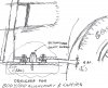
Jim, to piggyback on what Chuck said, I used a plumb bob to locate my new mounting points once I determined where my steering shaft should be. For me, it was centered between the clutch and brake pedal, then centered to the dash. This change required the spherical bearing to be mounted about 3/4" away from the factory hole and spaced up as high as it would go. This brings the u-joint pinch bolt head real close to the frame, but I prefer my steering wheel to sit a little lower.

Probably best to locate where you want your pedals and have the dash in it's final position FIRST before you drill your new hole for the spherical and flanged bearings.

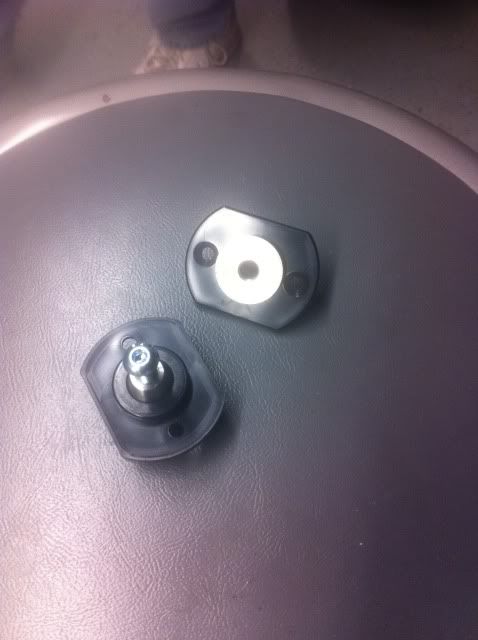
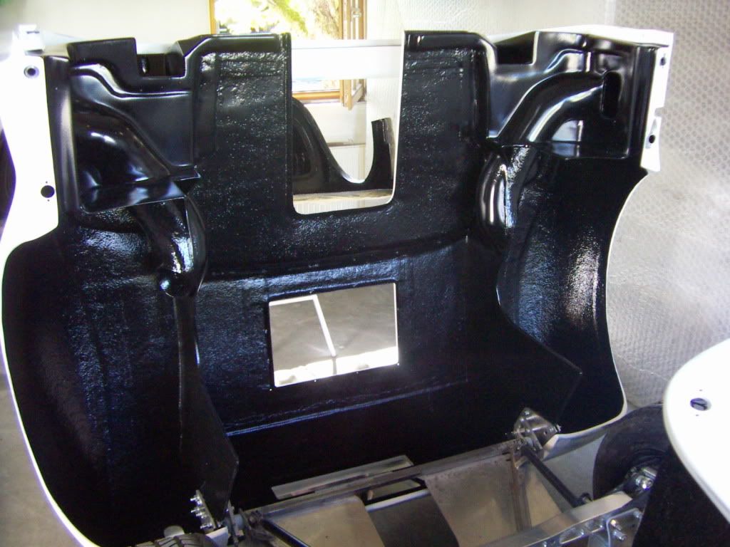
The flanged bearing behind the dash had to be relocated so it's centered with the dash steering cutout.

After this change, the steering wheel is now perpendicular to the centerline of the car, not angled off to the left when viewed from above, and it's centered in the dash.

Tom, Thanks for the idea and photos! I'm heading back out in the garage now....

@Fran - Thanks for your reply. I did check out the online manual, good photo documentation. It helped me figure out how the mount is attached at the dash with the servo thing... I knew I was going to get called out on my terminology with my previous post! :) I don't know what half this stuff is called but I do know what it's suppose to do! :)
 
Hi Jim

Steering shaft. Just a straight shaft from the rack to the position where you want it to be, works best in my opinion. Will give a nicer inclination for driving (not as flat) and the most footclearance. You may need to cut out some of the vertical chassis plate to clear and reinforce it with a bridge.

Check out my build log here
http://www.gt40s.com/forum/gt40-build-logs/24525-toms-rcr-40-trackracer-24.html#post316309

TOM

Beautiful work as usual Tom. Thank you for the link!
 

Chris Kouba

Supporter
Joints - I have been working a lot over the last couple of weeks trying to get the gaps and "rough" edges smoothed out.
GT40Joint4_zps290f093e.jpg


GT40Joint5_zps0af349a9.jpg

Jim,

If you got your roof to look like that (and your doors and clips) with weatherstripping in, I need to buy you a ticket to Portland. That looks fantastic.

When are you coming?

Chris
 
Jim,

If you got your roof to look like that (and your doors and clips) with weatherstripping in, I need to buy you a ticket to Portland. That looks fantastic.

When are you coming?

Chris

Weatherstripping is in... If you can promise me a sunny day then I'm there! :) Thanks Chris.
 
Ok... Someone have a photo of the correct orientation for the these? I think the protruded side goes up but.... Thanks

dowels_zpsf3b8334b.jpg
 

Randy V

Moderator-Admin
Staff member
Admin
Lifetime Supporter
If those are the alignment pins for your clips, The black plastic part goes in the clip and the stainless pin is screwed to the sill... or am I misunderstanding what i am looking at?
 

Chuck

Supporter
Those don't look anything like the clip alignment pins on mine. Don't recognize them. If, hypothetically speaking of course, they were alignment pins, I would point them upwards into the pocket on the clip. Perhaps there is a cone missing?

Give us another clue . . . .
 
The pin with the screw has a "conical" shape that you would think goes in the clip but the black plastic part has two holes that are counter sunk. The odd thing is the counter sink would be facing down which doesn't make sense. I think I saw these in Rob's car in one of his photos with the cone up. I also saw something like this on Jason's car but the flat side was facing up. Not sure which one is correct. I'll take more photos. Anyone have a photo of there pins?
 

Chris Kouba

Supporter
They are the alignment pins for the clips.

The allen head cap screw gets threaded into the sill, the black nylon gets recessed into the flange on the clip. I don't think I have a pic but will hunt around shortly.

CK

edit: found one-

Cone goes on the sill with the bolt through it threaded into the alu sill, black nylon insert (no pic, sorry) goes on the clip in the "correct" location.
GT+fuel+system+001.jpg
 
Last edited:
Thank you guys! Chris, so the black plastic flange sits flush with the aluminum or is it proud of the aluminum? Wouldn't that cause the rocker to not sit flush on the aluminum? I'm referring to the "squareish" shape part. I realize the round plastic part goes into the aluminum.

Appreciate the help!
 
OK...

the stainless pin is mounted to the rocker panel.

A hole to match the size of the round raised circle is cut into the lip on the bottom of the tail edge.The black nylon shoe is attached to the inside of the tail with the roundraised circle protruding through the hole.,

The 1/8 flange on the stainless steel pin then creates a 1/8 body gap when the tail is closed.
Due to differing thickness of the fiberglass layup, it may be necessary to smooth the mounting surface on the inside of the tail to give a flat, solid mount for the nylon shoe.
 

flatchat(Chris)

Supporter
A rough sketch of how they were originally intended ---but there's no wrong way to have them mounted -- why, they even use them quite effectively as door hinges
 

Attachments

  • Picture 217.jpg
    Picture 217.jpg
    136 KB · Views: 472
Chis,
thats similar to how we install them but we use the stainless pin to actually clamp the rocker panel in place...hence the flange on the stainless pin creates our body gap vs the flange on the nylon shoe...

This only for the RCR40...the SLC has a pocket moulded into the body for the nylon shoe....
 

Chris Kouba

Supporter
I realize the round plastic part goes into the aluminum.


Nope. Nylon (black) piece gets flush mounted with/into the flange on the fiberglass clip.

Be precise when drilling your holes because, like Fran says, you sandwich your sill panel between the stainless cone and the alu chassis to hold it in place (like in my pic). I can take a better pic for you later today or you can call if you still have questions.

CK
 
I got it! Thank you guys for the clarification... Honestly, I'm really good at building cars! :) Hey, some of this stuff is complicated! Two pieces on that one!
 
Sorry Jim

for beeing a bit slow with my comments

here you can see how the black nylon part is mounted from the inside of the rear clip.
PICT3610.jpg


I have used two locaters per side.

And here you can see tha stainless male parts located on the sill
PICT3691.jpg


TOM
 
Sorry Jim

for beeing a bit slow with my comments

here you can see how the black nylon part is mounted from the inside of the rear clip.
PICT3610.jpg


I have used two locaters per side.

And here you can see tha stainless male parts located on the sill
PICT3691.jpg


TOM

Not a problem Tom. I appreciate your post. I figured it out last night. I'm heading out in the garage tonight and get the front squared away. Thank you!

You guys have been so helpful. I really appreciate it.
 
Can anyone share the model number and location where I can purchase the Hartwell latches? The ones that Tom used? :) I know they are expensive but they do look nice!
 
Back
Top