Kiwi scratchbuilt

Hi Russ,

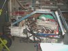
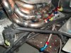
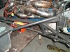
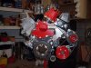
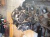
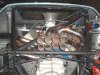
Good to see you back on the job. Have you had the engine assembly in the chassis for a trial fit with all the accessories in place ? We started life with the exhaust manifold plates as pairs but found it impossible to actually remove and replace with the engine in the car. We also had to remake / adjust a few of the oil lines to make the whole thing fit ! I thought things were tight in the Cobra engine bay but it was a doddle compared to the '40.

Iain
 

Russ Noble

GT40s Supporter
Lifetime Supporter
Iain,

I'm about to fit up motor/accessories/trans in the chassis shortly. I think it will all fit OK, I don't think the exhausts will be a problem but, just as you have found, the oil lines will be a tight fit. As always I'm not expecting any problems :lipsrsealed: :shrug:

I can't believe I said that!!:eek: :rolleyes: LOL
 
I can see it now, beautifully engraved on your headstone

"I'm not expecting any problems"

I recently used Plexus to bond some fiberglass together, the salesman enthusiastcally explained all the other things it was good at bonding, do you think it would be any good with teenage daughters ?

Iain
 
Ian,
Any bonding with teenage girls requires time and/or $$$$.Even then if the moon is not in the right phase or teenage boys are involved, it may not hold, leaving you to pick up the pieces:furious:

Bill
 

Russ Noble

GT40s Supporter
Lifetime Supporter
Jeez Iain, thanks for the epitaph!!

My kids have already said they think the chassis looks like a coffin!!

My daughters were teenagers a decade ago. You may find copious quantities of hundred dollar notes works better than Plexus for bonding with teenage daughters. But they're all sweet wee angels that can twist us round their little fingers aren't they!! :angel: :angel:
 

Russ Noble

GT40s Supporter
Lifetime Supporter
Finished and fitted the hydraulic release bearing.

Most of the donkey work was outlined in post #140 but I still had to fit the fluid supply and bleed lines and make the plastic locating buttons that were to fit in the old fork pivot bushes. The most convenient way to exit the bleed line was to drill a hole in the rear of the bellhousing and mount the remote bleed nipple on a bracket off the adjacent bellhousing bolt. The supply line conveniently entered through the redundant starter hole. It also made sense to shorten up the boss where the lines entered the housing, making for a neater setup and providing an easier path for the flexible lines.

Motor and trans can now be mated up for the last time hopefully and fitted in the chassis. That for the last time too hopefully!
 

Attachments

  • Concentric release bearing0214.JPG
    Concentric release bearing0214.JPG
    56.6 KB · Views: 374
  • Concentric release bearing0217.JPG
    Concentric release bearing0217.JPG
    49.3 KB · Views: 405
  • Concentric release bearing0218.JPG
    Concentric release bearing0218.JPG
    69.2 KB · Views: 413
  • Concentric release bearing0220.JPG
    Concentric release bearing0220.JPG
    66.3 KB · Views: 403
  • Concentric release bearing0222.JPG
    Concentric release bearing0222.JPG
    72 KB · Views: 454
I am assuming from the castings etc that this is a "standard" set up, If it wasnt I would be asking questions about the location of the bleed outlet on the release bearing which I would have expected to be at the top ?

Iain
 

Russ Noble

GT40s Supporter
Lifetime Supporter
Yes Iain that is a slightly modified Quartermaster unit. Those were my initial thoughts also and if I could, I would have positioned the bleed vertically. However packaging considerations dictated the choices, so it is where it is! Space is really tight in that bellhousing and it was not possible to mount it in any other position. Nevertheless quite a neat, tidy and compact installation I felt.

As far as I am aware, this is also the approximate orientation when it is fitted more usually in Fords, Chevs etc. so whilst theoretically it is not ideal, practically, I don't think there will be any problems.

I guess if the worst came to the worst, I could always tip the car on it's side to bleed it! LOL
 
Russ:
Nice to see you progressing. Nice install of the throwout bearing assembly.
Are you putting a pedal stop on your clutch pedal?
 

Russ Noble

GT40s Supporter
Lifetime Supporter
Motor and trans can now be mated up for the last time hopefully and fitted in the chassis. That for the last time too hopefully!

Well, silly me! :p: Fancy thinking it was going to be that easy!:furious:

Struck a minor stuff up, all of my own making. The rear of the motor won't sit down where its supposed to because the exhausts are fouling the shock tower braces on both sides.

When the pressure was on back in January as I fabricated the shock tower braces back to the sills, I did it without having the heads and exhausts in place. Unfortunately, now they both want to occupy the same space. That obviously won't work so I'll have to chop the braces out and redo them. Oh well, just as well I've got nothing else to do! :rolleyes:

Dave, no pedal stop as yet, but if I need one I'll fit it.
 

Attachments

  • stuffup0225.JPG
    stuffup0225.JPG
    86.5 KB · Views: 653
  • stuffup0226.JPG
    stuffup0226.JPG
    87.8 KB · Views: 594
  • stuffup0227.JPG
    stuffup0227.JPG
    85.3 KB · Views: 530
Russ:
Nice job on the headers, it looks like you are using 1 3/4" O.D. Tube. Really looks good on the motor. I had contemplated that size when I fab mine, and had some thoughts on whether it was difficult fitting everything up at the collectors with things being a little tight right there.
Also I suspect I am not running the output you have in your motor and mine may be more suited to 1 5/8" tube.
Keep up the great work.
Cheers
Phil
 
Russ
I can relate to the non fit, its like doing a drawing in 3d where you layer the detail on top of each sheet. Something allways gets in the way. I had the same problem when other bits wanted to occupy the same space as my water pump / altenator and ended up sticking them the side.
 

Attachments

  • All closed in 002.jpg
    All closed in 002.jpg
    54.4 KB · Views: 547
  • body fit 013.jpg
    body fit 013.jpg
    43.7 KB · Views: 454

Russ Noble

GT40s Supporter
Lifetime Supporter
Thanks guys. Reassuring to know other people do these stupid things!

Phil, you should be right with 1 3/4" tube. I have actually built stepped headers. They start off at 2 1/4" at the flange with an AR cone/chamber incorporated inside, then neck down to 1 3/4" before they step up to 1 7/8" for the middle section then 2" for the last section before the collector. My pipes were a bit of a juggle because amongst other things they had to clear the rear rollbar stays and diagonals. With your obvious skills you should have no problems.

I fixed the stuffup with the chassis tube and while I was doing that I decided to alter the rear combined top shock absorber/roll cage backstay mount to make it more user friendly. I originally had it with just a 1/2" bolt going through the lot ie chassis, shock absorber and rear subframe. It was a bit of a PITA to remove and more so to line everything up when refitting. So I decided to make something that would locate up on tapers and also enable the rear shocks to be removed without disturbing the subframe or vice versa. Previously removing the bolt disconnected everything.

Basically I machined up sleeve for the middle section that was welded to the chassis. An internally threaded shouldered sleeve with a taper on the leading edge then located inside this and mounted the shock while the rear subframe located on the outside shoulder and was guided on by an external taper on the rear of the welded middle section. A suitably profiled stepped washer/spacer was clamped by a cap screw which engaged in the shock mount threads and held every thing together tight. A picture is worth a thousand words! When I took these photos I still had to do some detail finishing.

The beauty of this set up is that if I want to remove the shock I just have to remove the capscrew and the threaded sleeve and voila the shock is out. Similarly, to remove the rear subframe I just have to remove the capscrew and stepped spacer. I can remove either the shock or the rear subframe and have the other remain in place. Not sure why I didn't do that to start with!!
 

Attachments

  • gearchange0254.JPG
    gearchange0254.JPG
    92 KB · Views: 428
  • gearchange0232.JPG
    gearchange0232.JPG
    58.7 KB · Views: 384
  • gearchange0233.JPG
    gearchange0233.JPG
    57.5 KB · Views: 336
  • 2009_0622gearchange0234.JPG
    2009_0622gearchange0234.JPG
    70.7 KB · Views: 422
  • gearchange0245.JPG
    gearchange0245.JPG
    72.3 KB · Views: 386
Hi Russ ......good to see some more progress on the car, I was just going back over the posts about the front and rear uprights you have constructed and was impressed at the weights you have achieved. I have sent the finished patterns to the casters and was there today to talk alloys and we are going for the 5008. I will get some photos asap and get them on the site as I know you were interested. The patterns turned out really well and hope they are a close look to the real thing, should have them back in a week or so. Nice to see some more progress, keep it coming.
Cheers Leonmac.
 
Russ:
Good idea on that mount. It seems that the bolt is in tension holding the subframe, and the tubular spacer carries the load from the shock absorber without stressing the bolt...I like it.
I went through the same "Why didn't I do that this way" with my shifter, and eventually scrapped the whole thing except the lever and ended up with a much simplified, smoother, and more positive action with less moving parts.
I am close to doing my headers, just waiting for the flanges to be cut from 3/8 ss plate, as I have a dummy motor in place for fitment.
I would love to hear what yours will sound like when fired up.
Cheers
Phil
 
Russ hi mate good to see the cold hasnt kept you out of the shed.
ctutch pedal stop, you will almost certainly need one with a concentric bearing release, as they dont have to move the 1/4 master very far to release, and as youve obvviously read the instructions youll no set up clearances are critical. we had to reduce clutch M/Cyl size down to 5/8" to limit travel as well as fit a stop.
BTW, NZSCC agm last sat, new rules, basicly super sprint is open slather, run what ya brung, might as well be Formula Libre under another name, look foward to seeing you out there
on a high note, finaly got the little clubby dynoed at last, 311hp and weighs 496kg should prove interesting
cheers John
 
Hi John.......Thats good to hear about the Super sprint class, as when I was in contact with them last year as to the allegability of a Can-Am style car they were talking restrictions on the class, ie Max engine size. so its good to see there might be somewhere to run. Did you ever finish the car you had for sale last year or did some lucky guy get a good starting point, it was looking quite good. Sorry for hijacking your thread Russ. Leonmac.
 
Back
Top