Hi Jack, What you have drawn is pretty much what I have done, I have also thought of the tapered shoulder but wasn't 100% sure if it was needed they 1/2" 8.8 grade studs with a slot in the tope to hold the stud while torqueing up the nut on the back side. At this point I have only done 1 so will look at the tapered shoulder on the next one. thanks for the advice. cheers Leon.

You are using an out of date browser. It may not display this or other websites correctly.
You should upgrade or use an alternative browser.
You should upgrade or use an alternative browser.
M20 Dreaming
- Thread starter leonmac
- Start date
Terry Oxandale
Skinny Man
I would love to understand the interactions between the threads on a bottomed stud when a backing nut is also applied. As I think through it, wouldn't the backing nut, to some degree, negate the tightening action accomplished in the bottoming out of the stud (opposing tensions)? I've often wondered if one chooses to do this, if the best thing wouldn't be simply a bolt or flanged stud having only an unthreaded shank throughout the bound pieces (simply a normal wheel stud), or a bottomed-out threaded stud (as Leon asked about) using threadlock, without the backing nut. I know that ARP specifically instructs the user of their studs to not bottom out the threads.
Hi Jack, What you have drawn is pretty much what I have done, I have also thought of the tapered shoulder but wasn't 100% sure if it was needed they 1/2" 8.8 grade studs with a slot in the tope to hold the stud while torqueing up the nut on the back side. At this point I have only done 1 so will look at the tapered shoulder on the next one. thanks for the advice. cheers Leon.
Loads on the 'pins' are going to be higher due to the smaller pcd and you only have 4 pins whereas most other cars have 5 or 6 pins on a larger pcd..
Power is applied via the hub flange and then pins which have to pass thru disc & adapter before engaging with wheel hub, so the more substantial you can make the pin in that area the better it should be. Braking forces also have to be considered, but as distance from wheel to rotor is less perhaps not quite as critical.... still a good reason not to have a potential stress riser in that area.
Would this be a better setup, increase the pin size, weld the single nut adaptor to the stub axle. this would mean the pins only hold the Disc and not the wheel on so if you managed to shear the pins the wheel would stay on
Attachments
Last edited:
Not keen on welding the adapter 'spud' on like that as it is now carrying car weight, how about welding adapter flange at OD of both flanges and just fitting the rotor hat between wheel and hub face like most willwood / coleman rotor hats these days, if using alloy rotor hats I think you would find that pin back nuts would tend to loosen against the alloy in use with fitment as per your drawing.... Terrys imagination will be going into overdrive on all this stuff without pics..")
Re the LH/RH centerloc nut thing we had a fairly big session on that a few years ago on Russ Nobles car I think if you want to dredge thru that, Jim C might be onto it with his explanation. I contacted a guy with the Aussie V8's & he said they use same thread both sides, but obviously they use air guns for all wheel changes, might be due to the corriolis ( spl) effect in the Northern Hem that causes all the yank wheels to fall off or just not enough spinach!!
Re the LH/RH centerloc nut thing we had a fairly big session on that a few years ago on Russ Nobles car I think if you want to dredge thru that, Jim C might be onto it with his explanation. I contacted a guy with the Aussie V8's & he said they use same thread both sides, but obviously they use air guns for all wheel changes, might be due to the corriolis ( spl) effect in the Northern Hem that causes all the yank wheels to fall off
or just not enough spinach!!
Last edited:
Terry Oxandale
Skinny Man
Tough crowd I agree wholeheatedly about welding the periphery of the adapter flange if you resort to that permanent option. I understand your extraordinary efforts to make this project matching the original as much as possible, but is there no means of using the typical wheel stud in your design?
I agree wholeheatedly about welding the periphery of the adapter flange if you resort to that permanent option. I understand your extraordinary efforts to make this project matching the original as much as possible, but is there no means of using the typical wheel stud in your design?
Last edited:
Tough crowd
Plus 1 on that Terry, Ive done that with the patterns for the turbines of the MKIV so that I can use 5 or 6 pin/studs with an imitation knockoff that clips in. Gotta be real sad day if all 5/6 wheel nuts fall off at same time
I hear ya Terry, and sometimes I think I'm being pedantic about little details. Then if I don't watch the little things pretty soon the big things won't matter and the whole thing will drift off and become "just a look a like" and not a "replica" That's why I have done things like making my B/H so it could take a Hewland and the hubs so they could take a real McLaren wheel. Also I view this as a Prototype and I may rear make a few things at a later date as the budget allows and I have seen that the Proto actually works. What I'm trying to say is these hubs as such may never see real service and only serve to trial fit the wheels and brakes etc and prove the design, I promise Terry there will be photos soon, Cheers Leon.
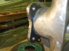
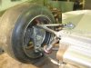
Hi Jack / Terry and anyone who is watching, I have heeded your advice and welded the adaptor to the flange, it also has the hub spigot on the stub axle pressed into the adaptor so its not just relying on the adaptor to hold the weight of the car. The disc hat slips over the centre and pins and is held on with the wheel I just have to change the pins as they are now to short as the hat is 10mm thick and I also have to increase the boss on the wheel by 10mm so the brake caliper doesn't hit the wheel centre. I have also started the bracket for the Caliper which bolts to the upright, the camera has made it to the workshop and once I have the whole thing done I will take some pics so you can see what we have been talking about for so long. Cheers Leon
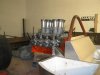
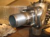
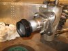
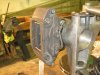
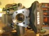
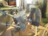
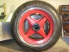
More time on the car today, I machined up the brake caliper bracket that will bolt to the front of the upright, Fitted the caliper and disc and then set the wheel in place. Still need to do some minor work on the lathe to get it completely fitted but the basic's are there and good clearance on the wheel and the track is within 1/2" so quite happy. I welded the hub adaptor to the stub axle so the drive pins just do that and don't hold the adaptor on although they do still have a nut on the back side to lock them in place. Anyway I have some photos (Ye Ha) I hope you enjoy (Terry) I chucked a photo of the block, heads and injection in as a teaser. cheers Leon.
Attachments
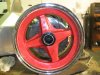
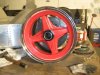
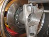
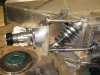
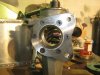
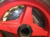
A few more photos, The bracket is held with 8mm bolts the shoulder goes into the alloy by 10mm so there is no stress at the thread transition point. I also changed the drive pins to 9/16" so I can Loctite them into the adaptor and not need the lock nut on the back or I can get some slim nyloc nuts ?? Once I have this all sorted I will do the other side and then finish the steering. Cheers Leon.
Attachments
Terry Oxandale
Skinny Man
Glad to see everything coming together with the front brakes and hubs. It all looks compact and quite effective. Are you using any high-angle bearings on top/bottom of the uprights, or standard angle?
When will you start on the rear uprights?
When will you start on the rear uprights?
Hi Terry/Mike, I'm only using std bearings, as there is only going to be a max of 4" travel the angle change is well within the range of the std bearing. The top link has about 3 degrees on it at ride height so I will angle the mounting bush so the bearing is at 0 degree at rest. The rear uprights are pretty much done, I just have to mount the Drive pins. I'm going inboard brake's on the rear. As for the Rad's ,I did see those ones on ebay but I know from importing books that shipping is prohibitive unless the stuff is on the West Coast. I was going to buy the second Pete Lyons "Can-Am Cars in Detail" book (I have the first one) The book was $285 and the shipping was $180, made it over NZ$500 so I would imagine those Radiators would be over $300 shipping I will try to find something in NZ.
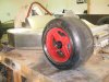
Well I have one corner self supporting, I put the tyre on the wheel this morning and fitted it all up to check turn radius to what it going to hit and pleased to say on full lock it just touch's the side of the tub but I can adjust that out with the suspension arms. The shocks that are in the photo aren't the ones Ill use but were right just to hold it up, that is at 4" ground clearance I will set it with 3'' up and 1" droop and probably run at 3" ride height so it will end up with 2" each way. Just to do something else today I also dragged out the T/A case mould and did some more on that for a couple of hours.
Cheers Leon.
Cheers Leon.
Attachments
Hi Leon
Its looking great, question ,your uprights will the arms travel through their motion without binding in the upright.
It looks tight.
Jim
Its looking great, question ,your uprights will the arms travel through their motion without binding in the upright.
It looks tight.
Jim
Good eye Jim, It does have the full range "JUST" but I have to relieve a little on the bottom joint and it will be good. Everything is tight in this area. I have some big "Brembo" calipers that I wanted to use but will have to re work the Wheels to get them in with the 300mm rotors, may look at this later. Cheers Leon
Back in the workshop the last 2 days, Started the bracket for the left hand side brake caliper, looked at and reset the engine in place as I have to start the front engine plate and finish the roll bar. This is actually going to be a very big job as it needs to be in the right place as once the roll bar is built there is no adjusting things later. So I bolted the B/H to the block and will attach the T/A case that will give me the centre line for the rear axle then I have to work out the height for the engine to sit because I have to be sure the rear deck will sit over it, The original car uses a much smaller Fly wheel and dry sump to get the engine low so I guess I will have to go the same route. I was hoping to use the 153 tooth ring gear but it requires 6" crank line to bottom of sump and that may put my engine an inch or so too high, I'm still doing measurements. Anyway I'm laying out all the rear suspension and gearbox so will get some photos up when its all set up. You should get a good idea of the rolling chassis.
Cheers Leon
Cheers Leon
Similar threads
- Replies
- 7
- Views
- 877