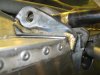
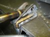
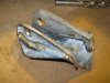
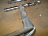
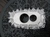
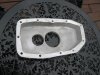
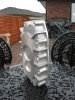
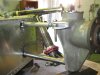
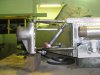
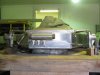
Well I have poured the first alloy for my Custom Transaxle and machined the case that it became. Its only a small part but it is better to start with the small parts and by the time you get to the big bits you should have things sorted. The part is the rear bearing retainer for the lay shaft and main shaft. There is a slight change in that this first T/A is only a 2 shaft and won't have the QC gears in the back this makes the box lighter and almost 3" shorter. From the Axle line to the rear will be 16". The area where the bearings sit is 15mm and the rest of the case is 10mm thick with the obvious ribs and bosses where the studs will attach it to the main case. Next part in line for casting is the diff section, once it is made then I can line up the other end of the gear stack and then I can make the main case. Anyway a couple of shots of the finished part. There is a casting that bolts to the back of this to cover and retain the bearings, I already have it I just need to drill and tape the holes, there is a provision to drive an oil pump off the back of the main shaft.
Cheers Leon.
Attached Thumbnails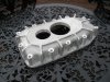
Cheers Leon.
Attached Thumbnails
![securedownload[1] (2).jpg](/data/attachments/56/56401-a343d9ceb6be44d3fe20c6e0f1438c05.jpg?hash=o0PZzra-RN)
![securedownload[1] (3).jpg](/data/attachments/56/56402-4ba21541396d62dd098a5cc9f88bd205.jpg?hash=S6IVQTltYt)
![securedownload[1] (4).jpg](/data/attachments/56/56403-5bbd0ba098a62a735fa61a2dd43057c9.jpg?hash=W70LoJimKn)
![securedownload[1].jpg](/data/attachments/56/56404-73d3a2550c37db86442fa94ef7b0098d.jpg?hash=c9OiVQw324)
![securedownload[2].jpg](/data/attachments/56/56405-6d63c2001642f71d51d666c15f103983.jpg?hash=bWPCABZC9x)
")