Looking good Leon!

You are using an out of date browser. It may not display this or other websites correctly.
You should upgrade or use an alternative browser.
You should upgrade or use an alternative browser.
M20 Dreaming
- Thread starter leonmac
- Start date
Terry Oxandale
Skinny Man
Nice Leon. Can't wait to see the steel crossmember in place and watch some other pieces put in place. Thanks for the update.
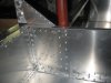
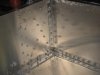
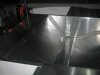
Hi Guys, I fitted the rear bulk head today and had a bit of a clean up on the table. I have used the SR rivets on the main stress area's (lenght of the cockpit side's to floor and the side pods and the rear bulkhead, front bulkhead and around the bottom lip) the internal bulkheads in the side pods are double laminated and double riveted so used pops on the floor but SRs on the sides. 700 holes drilled and 500 SRs 200 pops so far, I can see about 2000 by the time the tub is done (glad I got an air rivet gun) will send some more photos soon.
Cheers Leon
Cheers Leon
Hi Leon
the car outside clearly has a german license plate
i bet it´s this car build in germany
LMP Engineering - Specifications
close to my place(80 min away)
TOM
the car outside clearly has a german license plate
i bet it´s this car build in germany
LMP Engineering - Specifications
close to my place(80 min away)
TOM
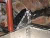
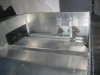
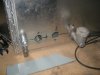
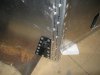
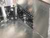
As always Terry your wish is my mission, I have put the rear bulk head in and cut the seat panels yesterday and today I bent up the roll bar and set it in the rear bulkhead. The bar fits into the box section that is the sides of the bulkhead, there are a couple of ways to secure it. 1) is to weld it in place 2) is to put 2 or 3 bolts through the box section and bolt it in place both of these mean I cant remove it (easly) and I would have to make the back stays removeable so I can work on the engine as the back stays bolt to the inlet manifold bolts as part of the way the engine is mounted, the engine is a stressed member NO chassis behind the rear bulkhead. The 3rd way is to weld a plate around the bar and bolt it to the top of the Bulk head. I need to get the local Scrutineer to have a look as they may ask me to run some bar work forward, I realy want to keep it the way it was originaly done, the modern rules may give me no option if I want to race it in proper competion??? Heres a few more photo's to show you what I mean. Cheers Leonmac
Attachments
Last edited:
Terry Oxandale
Skinny Man
Nice! So the steel is riveted to the tub directly and indirectly (onto a panel that is then riveted onto the tub), correct? The abrasion under each rivet head; what is that (de-burring process, cleaning, etc?)?
Thanks for all the updates. Very inspiring.
Thanks for all the updates. Very inspiring.
The abrassion is the deburring process, so you have to assemble the panels With tech screws, Drill all the holes, disassemble, deburr all the holes, apply the addhesive reassemble, Rivet the thing, 700 rivets so far, This takes time and patience but the end resault is quite pleasing so far. I hpoe to get the centre spine and the seat panels done in the next few days??? I think I will be heading off to work quite soon.
Cheers Leonmac
Cheers Leonmac
Hi Leon
Re deburring, you seem to be doing that by using an abrasive disc agaist the flat of the skin, which leaves the "buffcutt" marks. Why not just debur the holes using a countersink tool in a cordless drill. This will remove the burrs on the edge of the holes without marking the skin.
Or am I missing something?
Cheers
Fred W B
Fred you are right and I'm the one who missed something. Lucky the only surface that will be seen that has the buff marks so far is the small triangle piece on the trailing arm bracket, the rest will be covered. I will use the counter sink tool to do all the deburring on the top surfaces so there is no scuff marks.
Cheers Leonmac
Cheers Leonmac
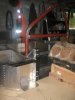
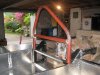
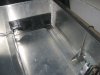
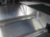
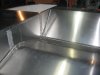
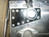
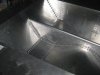
Hi, some more progress over the last couple of weeks, I have started the seat panel and the front suspension mounts which also incorporate the pedal box. Folding up the seat was abit tricky as the sides of the tub taper from 34" at the rear to 27" at the front, this made for a bit of tricky measuring and folding to make it fit nicely. At this point it is not riveted in yet and there is still a bit of work to get it 100%.
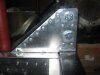
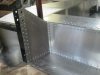
I then started the front suspension mounts and the pedal box as I need to get this all done and riveted in before I put the dash in place as there won't be a lot of room to work once the front is closed in. I have made the brake pedal from 50 x 25 x 1.5mm box section and the brace between the Plates for the suspension pickups is the same the plates are 3mm. I thought about doing the whole thing in alloy, but decided for the sake of a few grams steel was easier to work with the equipment I have at home.
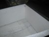
Also the fuel tanks are another thing I have in progress, I have lined the compartments with high density styrafoam, 20mm on the bottom and 3 sides and 40mm on the outside wall. My plan was to line the inside with fibreglass and then put the alloy sheet top on. What I would really like is some kind of rubber type product that I could spray or line and glue in. Any Ideas for this would be nice.
I have put up some more photos so feel free to give your opinion. Cheers Leon.
I then started the front suspension mounts and the pedal box as I need to get this all done and riveted in before I put the dash in place as there won't be a lot of room to work once the front is closed in. I have made the brake pedal from 50 x 25 x 1.5mm box section and the brace between the Plates for the suspension pickups is the same the plates are 3mm. I thought about doing the whole thing in alloy, but decided for the sake of a few grams steel was easier to work with the equipment I have at home.
Also the fuel tanks are another thing I have in progress, I have lined the compartments with high density styrafoam, 20mm on the bottom and 3 sides and 40mm on the outside wall. My plan was to line the inside with fibreglass and then put the alloy sheet top on. What I would really like is some kind of rubber type product that I could spray or line and glue in. Any Ideas for this would be nice.
I have put up some more photos so feel free to give your opinion. Cheers Leon.
Attachments
-
 Rear Subframe 001.jpg26.2 KB · Views: 476
 -
 Rear Subframe 002.jpg33 KB · Views: 498
 -
 Rear Subframe 003.jpg34.7 KB · Views: 466
 -
 Rear Subframe 004.jpg41.7 KB · Views: 477
 -
 Rear Subframe 005.jpg34 KB · Views: 455
 -
 Rear Subframe 006.jpg29.7 KB · Views: 460
 -
 Rear Subframe 007.jpg29.3 KB · Views: 445
 -
 Rear Subframe 008.jpg21.3 KB · Views: 461
 -
 Rear Subframe 009.jpg19.7 KB · Views: 459
Terry Oxandale
Skinny Man
Leon,
Nice! Must resist doing the same thing....... Seriously though, I reallly want to do what you're doing, but I've got two low-pressure pumps, fuel hose, and dry-sump pump priming access under/behind my seats, so I really must rely on a removeable seating tub, but I'm thinking now that perhaps a hybrid design may work. perhaps at least a walling up around the coolant tubes is this sheeting's ability as a heat sink and to conduct heat to the floor of the seat tub.
Nice! Must resist doing the same thing....... Seriously though, I reallly want to do what you're doing, but I've got two low-pressure pumps, fuel hose, and dry-sump pump priming access under/behind my seats, so I really must rely on a removeable seating tub, but I'm thinking now that perhaps a hybrid design may work. perhaps at least a walling up around the coolant tubes is this sheeting's ability as a heat sink and to conduct heat to the floor of the seat tub.
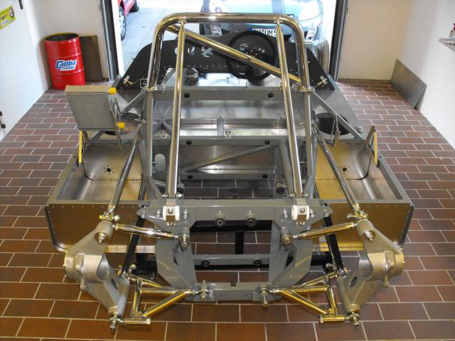
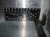
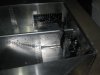
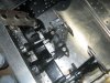
Hi Guys. I have working away on the pedal box and front suspension mounting, and boxing in the rear subframe. The rivets on the front suspension have washers on the back to give a little extra resistance to the rivets pulling through the alloy. I have also turned up the last of the spuds for the rod ends. Next thing is to fit the centre spine and finish the seat area and fit the seat belt mounts. Then I will start the dash and top mounts for the suspension. I have put up some more photos so let me know what you think, just for intrest the black you can see is the only steel in the whole chassis.
Cheers Leon. No photos , computer is not playing the game tonight
Cheers Leon. No photos , computer is not playing the game tonight
Lets see if this morning is better.
Attachments
-
 my pictures 031.jpg30.9 KB · Views: 464
 -
 my pictures 034.jpg31.7 KB · Views: 441
 -
 my pictures 041.jpg33.8 KB · Views: 438
 -
 my pictures 036.jpg27.1 KB · Views: 445
 -
 my pictures 047.jpg35 KB · Views: 432
 -
 my pictures 048.jpg52.9 KB · Views: 426
 -
 my pictures 050.jpg39.7 KB · Views: 460
 -
 my pictures 051.jpg38.7 KB · Views: 475
 -
 my pictures 052.jpg37.8 KB · Views: 431
Terry Oxandale
Skinny Man
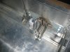
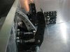
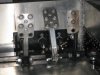
Tub is looking real nice Leon. I'm interested in the front lower arm mounting point (adjacent to the master cylinder). The threaded (?) plate sandwiches the aluminum panel to the inner steel subframe so that the aluminum and steel share in the distribution of lateral forces on the single shear pin (bolt). Correct? My first thoughts were on the shear potential at the transition from shank to threads on the bolt. Is the un-threaded portion of the sleeve in the outer plate designed to mitigate this (shank is supported by penetrating into the unthreaded portion, thus removing the shear stress at the thread/shank transition?
Trying to learn all I can...
Trying to learn all I can...
Last edited:
Hi Terry. There is no thread section of the bolt in the bracket, The shank goes right through, if you look you can see most of the thread out side the nut in photo 9 I'm also using 1/2'' grade 8 bolts. The original car also mounts the tube arm that holds the front of the bodywork off the top and bottom suspension "A"arm bolts, the top link bolt also locates the shock on the same bolt, its a double shear bracket. I've just spent the morning folding and mounting the centre spine, I've had it cut out for weeks and was in a flap trying to figure out how I was going to roll the top as it is only 1" wide. The end result was to stick it in the vice clamped between some wood and bend it over a 1'' tube and then with a lot of hammer beating and about 3hrs work it done and looking quite good. I will now do the hump under the knee and it will be finished and I can start the dash. will put up some photos when done. cheers Leon
Leon,
Are you using a panel cement when you rivet the panels together? Look's good.
Dave
Are you using a panel cement when you rivet the panels together? Look's good.
Dave
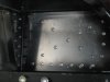
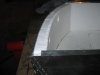
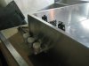
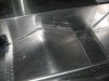
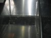
Some Photos of the centre spine and seat area, The seat bottom will have 5mm of cedar and then another sheet of alloy. the reason is 2 fold 1) the rivets holding the back and bottom of the knee hump are riveted from the bottom so the ugly side is seen, this will be covered. 2) a bit of protection for my bum, the thought of 1.6 mm of alloy between me and the road at 180mph ??? I have still got the left side knee hump to do but I've run out of adhesive and rivets so I will have to get some tomorrow. 1500 rivet's so far. Cheers Leon
Attachments
Last edited:
Absolutely stunning work Leon. I can't wait to see this car in the flesh.
BTW, you didn't feel a need to box in the last (front) side of the brake pedal? The side flanges are in compression and IMO could relatively easily distort and fold up particularly if subjected to a little bit of a twist from heel and toeing. For the sake of a few grams of sheetmetal (with lightening holes in if you want) to stabilize them......
However maybe the flanges are sufficiently over engineered that it is not a problem. Obviously your call. Just a thought.
I am very impressed with the quality and progress of your work to date. Keep it up.
Cheers,
Russ
Similar threads
- Replies
- 7
- Views
- 878