Jac, the questions just keep coming...many thanks for your help.
The cam is a Crower 50230 and yes reading the specs, it has 4 deg of advance ground in.
260 Dur intake and 266 Dur ex.
does this mean that my timing mark (TDC) would appear advanced via the strobe?NO
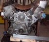
Even when i had it running at what I thought was its best, I was getting intermittent backfiring thru the carbs,Without being there hard to give definite opinion on that.
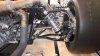
Can I still check the cam timing once assembled as a runner?Yes by checking for true TDC with stopper in #1 cyl and then doing an inlet valve fully open centreline check we/you can check the actual cam position, but if its not correct the front timing cover will need to be removed to do so.
I have attached a scan of the cam build sheet.
Cheers
Russell

")