
You are using an out of date browser. It may not display this or other websites correctly.
You should upgrade or use an alternative browser.
You should upgrade or use an alternative browser.
Mclaren M8b replica (visual)
- Thread starter russell keach
- Start date
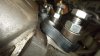
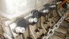
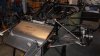
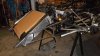
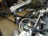
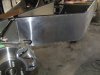
Fred, see the attached pics to see how I accounted for the angle of the inlet studs. The spacers are bored tight for the studs / bolts and then cut with a 1mm blade as close to the angle as poss. then welded to the inlet manifold base. I use longer bolts screwed in and the lock down with the nut, it saves the alloy threads. (same for the exhaust flange bolts)
Cheers
Cheers
Attachments
Hi,
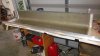
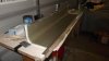
A bit more progress, went and bought my resin and cloth yesterday, it was cheaper by $50.00 to buy a 30kg (66mtr) roll from the wholesaler than buy 30 mtrs from the discount marine shop? I should have enough cloth to make both the mould and the final body.
Fortunately I had kept the body side mold which was made from rolled steel so the finished panel requires very little work apart from cutting to shape. One little trick i learnt was to lay aly angle bar along the top edge which produces crisp sharp 90deg corners along that top edge. This forms a lip where the top body panels sit down onto and provides a good sharp body join. The aly bar just pops off once cured.
Once these panels are cut to shape and fitted then the chassis is all but constructed and I can then start thinking about engine install and the wiring.
This time I am running an electric pump so that we can run down the engine rather than just idle off a hot motor. All the aly pipe work from the radiator has been run to the rear of the chassis waiting to connect.
The plan is to get the chassis to a roller stage then store it somewhere whilst I make the body work.
Attachments
Hi Russell, I see you are using the "Chopped Stran" cloth. Are you going to make a "buck" then a "mold" then the body?? In my case where I'm taking the body straight of the Buck I'm going to use the fine weave cloth as you can get a really smooth finish on the top, I've been watching lots of tutorials on Youtube. Can I ask where you bought you fiberglass supplies from, I was looking at the "Fiberglassshop" in Hamilton. They are wanting about $600 for a 100mtr roll of 400g woven cloth and $500 for 20ltr of resin and hardner, how does that compare to your supplier?
Looking forward to watching your body progress, Cheers Leon
Looking forward to watching your body progress, Cheers Leon
Leon, yes the long hard way at this stage, I have two options....make a male mold to a reasonable standard and then work the body surface from that or go the whole hog and make a buck, then the mold then the body which hopefully would require very little finishing. By doing the mold, I have 'insurance' and could possibly sell one or two to recover some cost. At least I could store the f/glass molds versus the timber buck.
My cloth and poly resin came from NZ Fibre glass as I have bought considerable over the years. My cost was $180.00 for 20kg of resin And about $200 for the 30kg of 450 gram cloth. All told including 4ltrs of acetone and a box of gloves, it cost $398.00.
I would be happy to get what you needed and you could collect from here if that helps.
All those smelly memories came back doing my first side panels moulding yesterday. Really need good breathing mask and to be well organized.
Re the finished surface, i have used a 'blinding cloth' first which is almost like tissue paper and you end up with a very smooth surface with no glass shards.
Really keen to get started on the body but a few more hours work yet on the chassis....good thing take time.
Cheers
Hi there, this one is discussion...
When I built my first Mclaren, I had the radiator in the side pod and felt that it was getting enough air to cool. I always had cooling issues so put the next size radiator up front in the conventional position and whilst it was better, it was still not perfect by any means. Many people have looked over that car with no comment on the lay out, we all often queried the mechanical water pump`s efficiency? Now that I am in the fabrication / assembly mode on the second car, a very knowledgeable race car builder who noticed immediately that I was flowing the radiator incorrectly (same as previous car). Both were / are plumbed out of the heads down to the bottom inlet, thru the radiator out the top, thru to the pump then thru the block and so one.
This time I am plumbed up the same way except that this time I am running an electric pump dragging from the radiator and pushing to the motor block. This set up is direct and straight forward and could be changed for this car. I plan on leaving status quo and converting the radiator into a triple pass to ensure that water stays in the radiator for a longer period of time. I do not have a picture of the old car front mounted.
Your thoughts as now is the time to change.
Cheers
Russell
Attachments
Terry Oxandale
Skinny Man
My understanding of why the water goes IN at the TOP of the radiator is because if air is introduced, or water escapes from the system, you will always be circulating water if drawn from the bottom of a partially filled radiator. Other than that, an airless system (does such a thing exist?) shouldn't make much difference on a forced-flow system. I'm using the electric pump, with water flowing in at top of radiator, out at bottom, and into the heads first (which I would promote with any motor), then out of the block, with the water pump pushing directly into the heads to insure the least amount of pressure drop before it enters/exits the motor. I've never had a heating problem...yet. BTW, the radiator I'm using is a typical single pass, 3" X 26" x 15"core. The shrouded fans only come on if no forward movement airflow exists. The aluminum ducting is sealed around the radiator to the point where very little bypass airflow exists, thus all inlet air/ram air must pass through the radiator.
I used well-nuts to mount my radiator (which uses side plates much like you're using) to isolate the radiator from a solid mounting configuration only due to a concern of chassis flex transfering to the tank/core bonding.
I used well-nuts to mount my radiator (which uses side plates much like you're using) to isolate the radiator from a solid mounting configuration only due to a concern of chassis flex transfering to the tank/core bonding.
Last edited:
That's interesting about pumping to the heads and out of the block, When you think about it the heads are where the heat is created so it makes sense to give them the coolest water. Also about sucking from the bottom of the radiator, any drop in fluid will affect the flow if you suck from the top. I have seen a SBC with water plumbed to 3 points on the head and that was because the back of the heads get hotter due to the poor flow in the std set up, my intake manifold has provision for front and rear water for the heads and I was intending to use this system.
Russell, is there a reason you have to suck from the top of the radiator?
Good ideas on this, makes one think about ones previous set up. Here's another one. If you are running 2 radiators, how would you plump them: A) suck from one side, into the engine, out to the other side through and across to the suction radiator or B) suck from both and return to both. Simply put : in parallel or in series?
Cheers Leon.
Mine are set up in parallel pulling water from the bottom of the radiators, so far no over heating although it has only travelled 600 feet total under power to date. Second 300 feet was just a few minutes ago. If I was setting up this system today I'd use an electric pump, without a doubt :helmet:
Just makes service and possibly packaging so much easier.
Just makes service and possibly packaging so much easier.
Terry Oxandale
Skinny Man
Mine are set up in parallel pulling water from the bottom of the radiators, so far no over heating although it has only travelled 600 feet total under power to date. Second 300 feet was just a few minutes ago. If I was setting up this system today I'd use an electric pump, without a doubt :helmet:
Just makes service and possibly packaging so much easier.
I would think this would be more efficient than a series arrangement in that the second radiator water is cooler, and hence less effective in transferring heat to the air.
Andrew Robertson
Supporter
Hi Russell,
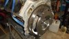
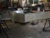
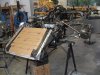
In the M1b replica I run a cross-flow radiator but like the others have said, I go from a small filler/header tank at the heads to the TOP of one side tank. I pull from the bottom of the other side using a 55gph mezzeire electric pump, then feed that into flanges where the original water pump would have mounted on the block. I also paid close attention to manging air in the system - I run a 2mm bleed back to the header/filler tank from the top/back of each head and from the top of each of the two side tanks on the cross-flow radiator. I also put a dam across the front of the air exit opening in the front body to create as much low pressure at the exit as poss. In a 20min sprint race my water temp does not get above 85C, and I'm making 600hp.
In the first photo you can see the 2 x -12 lines (that comes from the header/filler tank mounted at the front of the heads) entering the top LH side of the radiator. The electric pump is just hidden from view and is attached directly to the hose coming off the bottom of the RH tank. You can also see the bleed.
In the second photo you can see the dam added to the air exit.
Hope this helps.
Cheers, Andrew
Thanks for all the feed back, Yes when you do a Google search it clearly shows...in the top and out the bottom. Because I have not mounted the electric pump yet, I have the option of where I place it. I like the idea of the water flow out from the bottom, thru the pump into the heads, thru the block and back around into the top of the radiator and can achieve this without any physical changes. I am sure that this explains why the previous car was always fussy with its temp.
Cheers Russell
Cheers Russell
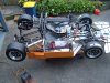
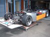
Side panel fit.
Fitted the side panels yesterday and starting to look like something. Pleased with the fit and I will paint them on the car. Had a good look at the plumbing and with the pump now mounted on the opposite side pulling from the radiator bottom, we will be pushing directly thru the heads, around the car to the top radiator inlet, problem solved. I will still modify the radiator to triple pass.
Cheers
Russell
Attachments
Similar threads
- Replies
- 2
- Views
- 427
- Replies
- 8
- Views
- 667
- Replies
- 16
- Views
- 2K
- Replies
- 0
- Views
- 689