S2's Build Thread

Scott

Lifetime Supporter
John,

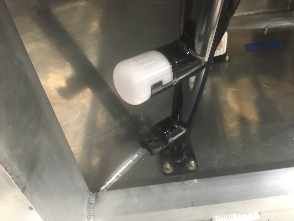
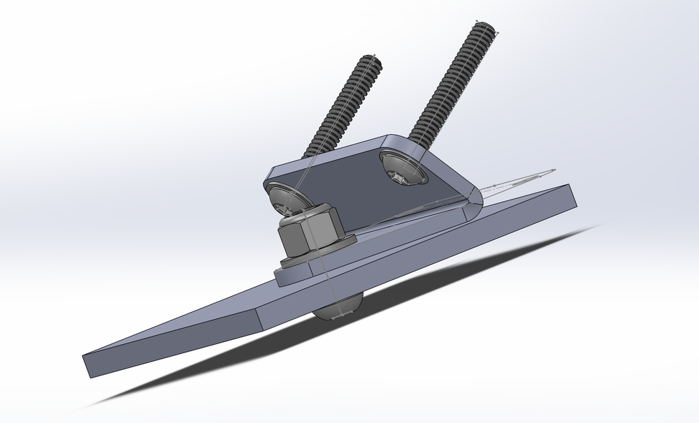
The rubber was the same that I used on the chassis and it was cut to fit the brackets. I am going to use one additional bracket under the large beam that runs across the tank to keep the tank from rocking backwards. The part numbers in the table below have links to the specs. You could get away with just one piece of the rubber, but two means that you don't need to be careful:
<table>
<tr><th>Qty.</th><th>Part Number</th><th>Description</th><th>Unit Price</th></tr>
<tr>
<td>4</td>
<td><a href="https://8020.net/4334.html">4334</a></td>
<td>80/20 Aluminum 4 Hole - Wide Gusseted Inside Corner Bracket</td>
<td align="right">$6.25</td>
</tr>
<tr>
<td>2</td>
<td><a href="https://8020.net/4134.html">4134</a></td>
<td>80/20 Aluminum 4 Hole - Wide Gusseted Inside Corner Bracket</td>
<td align="right">$5.65</td>
</tr>
<tr>
<td>2</td>
<td><a href="http://www.mcmaster.com/#1312n43/=13pgekr">1312N43</a></td>
<td>2" x 36" x 1/4" Ultra-Strength, Self Adhesive Neoprene<
(Durometer 70A - Hard)</td>
<td align="right">$29.98</td>
</tr>
</tbody>
</table>

I ordered the 80/20 parts from eBay. The shipping on a per part basis is really high but they explain how you can combine shipping.
 
Last edited:

Scott

Lifetime Supporter
Does anyone know how to get the new steering column to tilt? I was expecting some sort of lever, but the only way I was able to get it to work was by using a screw driver to release the pawls on the underside of the steering column.

In addition, does the steering column telescope? If so, how?
 
I have the Oldsmo-buick column (as opposed to the XLR), my column is manual. There is a lever that came with the kit, black plastic (curved) handle, metal on the opposite end. It inserts into another metal lever on the left side of the column. You can actuate the tilt without the plastic lever inserted, but without the leverage of the handle, it does take some effort.

A.J.
 

Scott

Lifetime Supporter
...Superlite sent me the missing manual tilt lever.

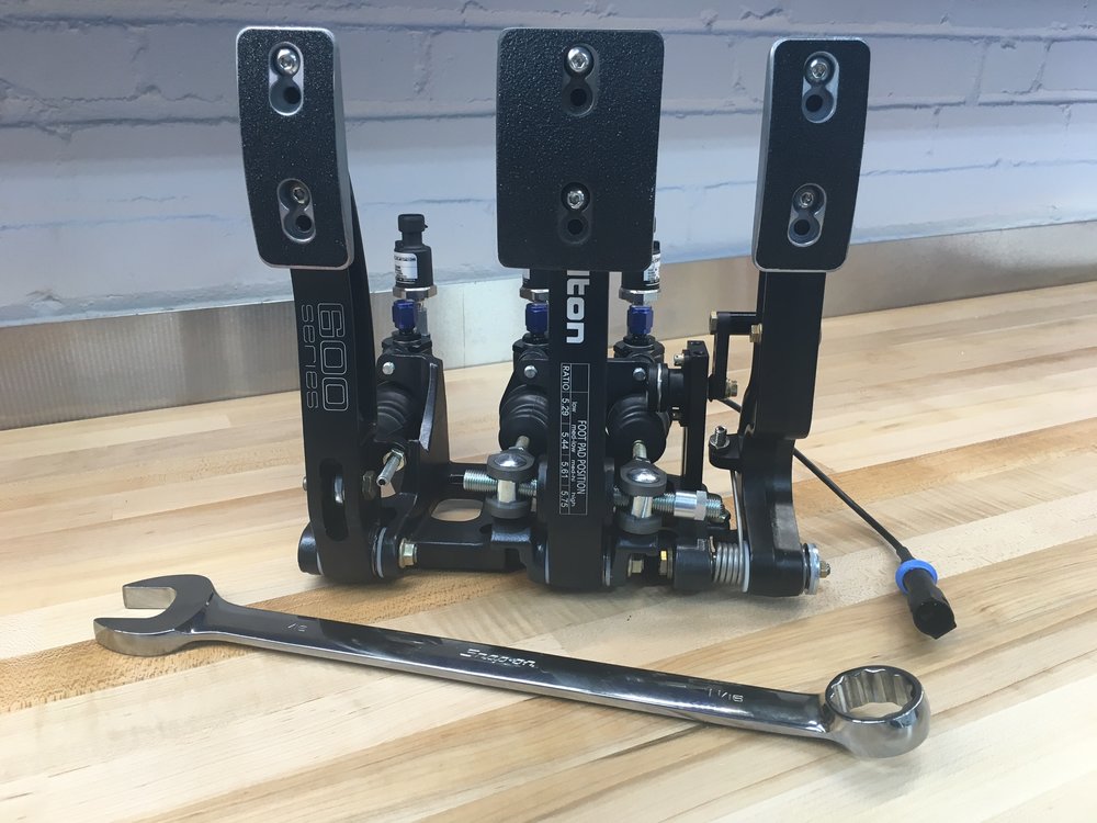
I finished the pedals today and I did a few different things. I upgraded the Wilwoods to Tiltons because I believe the Tiltons are superior and they use a -4 AN fitting for the reservoir feed rather that a rubber hose and barb, and they have an additional -3 AN fitting on the pressure side.

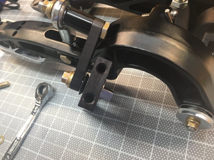
I also purchased Titlton's throttle linkage kit. Like everything Tilton, it's very well made. However, I had an issue with the lock nut on the max travel stud hitting the bracket. I checked things out multiple times and figured that I could grind the bracket, but that didn't seem right for Tilton quality, so I called their tech support and sent them some pictures. They called me back about an hour later. Apparently the holes in the bottom of the bracket are asymmetrical and the shaft had been installed backwards at the factory, thus moving the bracket slightly towards the throttle pedal. The picture below shows the asymmetrical bottom (the top holes are symmetrical). After taking it apart and reassembling it everything was fine.

IMG_0883.JPG


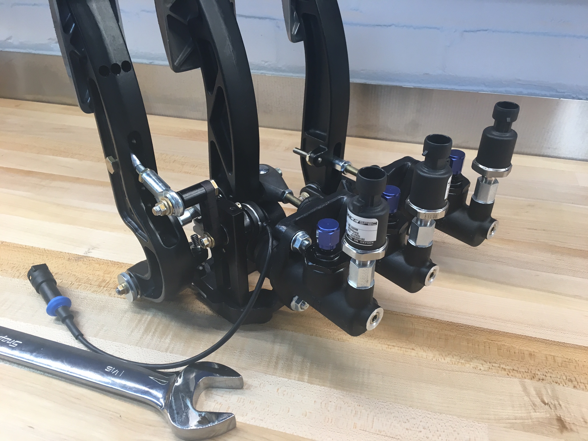
I won't use the supplied brake pressure switch. Instead I added high-end pressure transducers on the font brake, rear brake and clutch master cylinders. This will enable me to log the values and have the MoTec Power Distribution Unit (PDU) take actions based on the pressure.

The pressure sensor required a 1 1/16" wrench to tighten, which is the first time that I've used that wrench. Ironic that the tiny pressure sensor required a wrench much larger than all of the manly suspension pieces.

All of this resulted in a very clean installation.
IMG_0885.JPG


IMG_0886.JPG
 

Scott

Lifetime Supporter
Ron,

It's not a switch, but rather a transducer that outputs a variable voltage:

  • 0 to 2000psig
  • .5 - 4.5V Output
  • -40° to 257° F Operating Temperature
  • ±1% Total Error Band Accuracy
  • Less than 1ms response time
  • Less than 500msec warm-up time
  • 1/8" NPT Male Thread
  • Delphi Metri-Pack Mating Connector
  • Manufactured in the USA
I bought it from RaceSpec, who is doing my MoTeC install and I assume they white label it. To use it to switch the brake tail lights on/off I'll configure a threshold value in the PDU to toggle an output on/off.

It's not cheap ,but it appears to be very well made and the Race Spec guys have a lot of good experience with it. Here's the URL.

https://racespeconline.com/products/racespec-pressure-sensors?variant=16635733313
 

Ron McCall

Supporter
Ron,

It's not a switch, but rather a transducer that outputs a variable voltage:

  • 0 to 2000psig
  • .5 - 4.5V Output
  • -40° to 257° F Operating Temperature
  • ±1% Total Error Band Accuracy
  • Less than 1ms response time
  • Less than 500msec warm-up time
  • 1/8" NPT Male Thread
  • Delphi Metri-Pack Mating Connector
  • Manufactured in the USA
I bought it from RaceSpec, who is doing my MoTeC install and I assume they white label it. To use it to switch the brake tail lights on/off I'll configure a threshold value in the PDU to toggle an output on/off.

It's not cheap ,but it appears to be very well made and the Race Spec guys have a lot of good experience with it. Here's the URL.

https://racespeconline.com/products/racespec-pressure-sensors?variant=16635733313


Scott,

Thanks for the info but I was referring to the drive-by-wire throttle switch that you attached to the Tilton 72-792 throttle linkage . I assume that you are using the TPS280DP-type rotary sensor from Penny & Giles but I haven't been able to find a retail source .

Ron
 

Scott

Lifetime Supporter
LOL I had the same issue... after spending two weeks looking for a reseller I finally got a quote with a 6-8 week lead time. Then I posted in this thread and another member replied that it was rebranded by Jenvey as part number TP8LH. I bought it here:

TP8LH - Fox Injection
 

Ron McCall

Supporter
LOL I had the same issue... after spending two weeks looking for a reseller I finally got a quote with a 6-8 week lead time. Then I posted in this thread and another member replied that it was rebranded by Jenvey as part number TP8LH. I bought it here:

TP8LH - Fox Injection


Thanks!!!
Does anyone know if this sensor will work with a Ford engine management system?

Ron
 

Scott

Lifetime Supporter
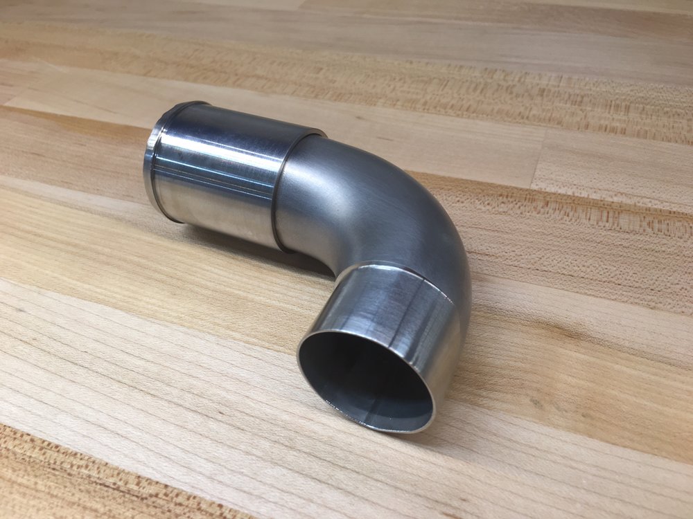
After spending time thinking about how to solve the issue of the water pump outlet tube hitting the chassis, I decided to copy pnut... I had John at Design Enterprises build me a custom part. He machined one end of a stainless steel 90-degree elbow so that it can be press fitted into the water pump. He then machined an adapter from a solid block of stainless steel and TIG welded it to the other end. The adapter serves two purposes: it provides a pronounced bead so that the silicone coolant tube won't slip off and it transitions from the pump's diameter to stainless cooling tube's 1.5" diameter.

He did a really nice job, but some of the weld created a ridge on the inside edge which I filed smooth to reduce turbulence. I also decided to refinish the raw tube to give it a satin patina. I'm happy with the looks and it provides the best possible flow given the limited space.
1472952335512
 

Scott

Lifetime Supporter
I’m going to need to design some parts to be CNC’d or 3D printed. I have no CAD skills and although I bought a 3D printer, a MakerBot 2x, a couple of years ago, I never fired it up. So it makes sense to do something simple first...
<?xml:namespace prefix = "o" ns = "urn:schemas-microsoft-com
FONT> <P><BR><FONT face=adobe-garamond-pro>I chose <A href=
Autodesk 123D because it's free, it's approachable by beginners and it has pretty good reviews. In terms of researching packages I found this decision graph and this summary list very useful.
<o:p></o:p>
After designing the part, I decided that I wanted to go back and change the fillet on an edge... well the only way to do that is by clicking undo until you get to that step (assuming that the steps are still in the buffer) and then manually redoing all of the subsequent steps. The reason for this is that it's using a 'direct modeling' approach. When you make a change to a solid, such as cutting off a piece or applying a fillet, it's gone. There is no way to get it back other than undo. Parametric-based CAD stores all of the steps and you can go back to any step, change it, and then have that change automatically rippled forward. These packages are usually more expensive and more complicated to use, but that's the direction I'm going. I'm thinking about SolidWorks which is both expensive and overkill for what I'm doing.
<o:p></o:p>
I did a test print using the 3D slicer that came with the MakerBot. I would show you a picture of it but my wife threw it out thinking it was some 'Lego junk' -- apparently my kids shouldn't leave their Lego stuff anywhere near the kitchen. In any event, I wasn't crazy about the quality of the print so I bought and installed Simplify3D, a pro-level slicer which did a much better job. However, I couldn't get it to communicate to the printer via USB and the SD card on the printer wasn't working. Frustrated, I searched for a local 3D print shop. I found 3D Hubs which enables you to upload a design and get instantaneous printing quotes from nearby shops. I picked Charles River Maker which is all of 3.4 miles away and had my part printed (they use Simplify3D as well). In the picture below you can see the white, 3D-printed part on the top coupler compared to the bottom coupler which doesn't have the part.
1473720636573

</P><o:p></o:p>
<o:p>
1473719441586
</o:p>
 
Ron,
That Penny-Giles sensor looks pretty similar to the one TWM/Borla uses on their stack injection units. I have one on mine and no issues. Throttle Position Sensors

Scott,

Thanks for the info but I was referring to the drive-by-wire throttle switch that you attached to the Tilton 72-792 throttle linkage . I assume that you are using the TPS280DP-type rotary sensor from Penny & Giles but I haven't been able to find a retail source .

Ron
 

Scott

Lifetime Supporter
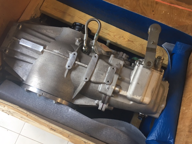
I received my Ricardo today! Since I have an aftermarket crank, so I’ll need to get a special flywheel from RCR. In any event, I know that it has an internal pump and I’d like to connect an oil cooler and thermostat.

Can anyone recommend a good thermostat? I’m looking at Improved Racing, but I’m not sure which is best. Oil Thermostats | Improved Racing

My guess is that the cooler dimensions will be driven by where I can fit it, but what is the recommended capacity?

1476413804013
 

Ken Roberts

Supporter
I use a Improved Racing FSM-165 thermostat on top of my Ricardo. I built a robust bracket that attaches to the DOM tubing. The trans cooler in the second picture is a Setrab 625. A Spal "puller" fan is used to aid cooling when needed. I attached a oil temp sensor in the Ricardo drain plug.


I also use the Improved Racing for the Ricardo but from memory I have the FSM-145. I mounted it on the chassis rail near where the trans cooler is installed in the side vents.
 

Attachments

  • 12829529_10153483036367914_3733245498537263271_o.jpg
    12829529_10153483036367914_3733245498537263271_o.jpg
    191.4 KB · Views: 495

Scott

Lifetime Supporter
Thanks Ken and Stu, I now need to figure out where all of the coolers are going!

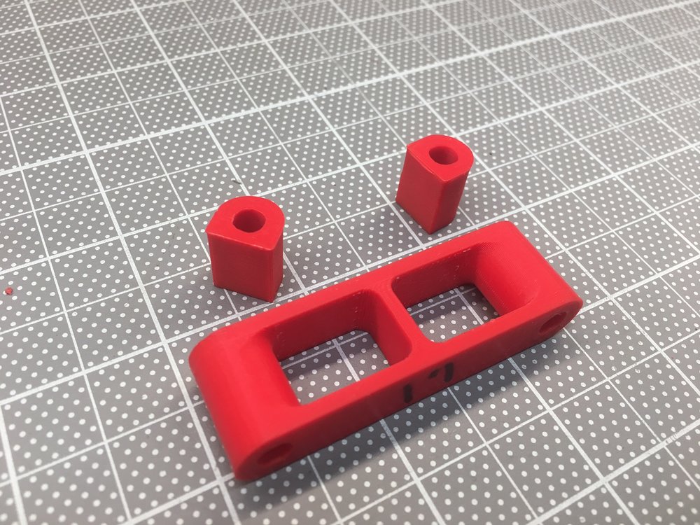
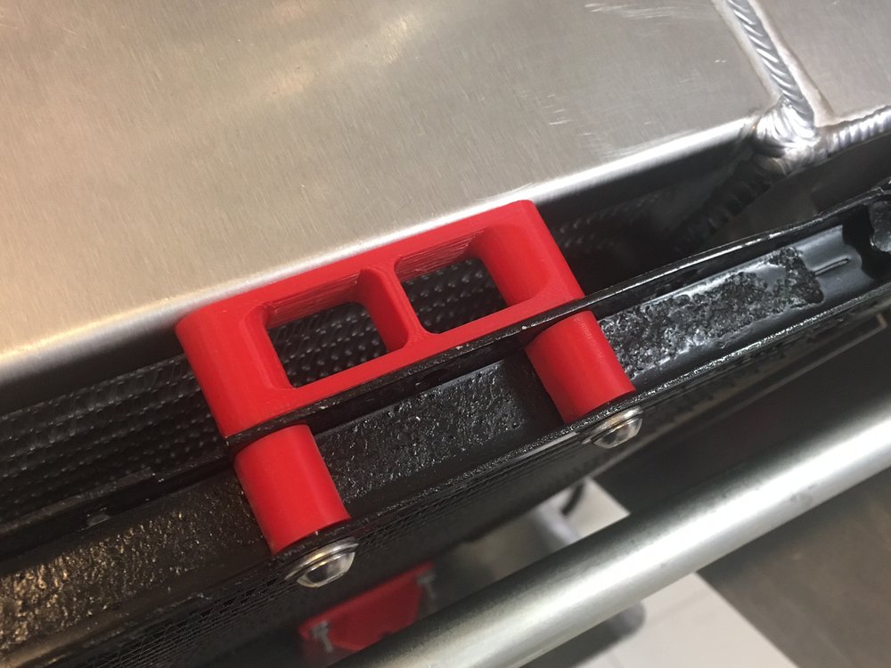
I designed and printed spacers and brackets to mount the condenser in front of the radiator. These are printed in medium quality mode in ABS. The final print will be in high quality mode in nylon, but I need to upgrade the extruder and several other parts of my 3D printer to handle the higher temperatures. The manual indicated that spacing should be 1/2" to 3/4" and I went with 3/4". Let me know if anyone thinks it should be different... it's easy change!
<NOSCRIPT></NOSCRIPT>


<NOSCRIPT></NOSCRIPT>

I designed the bottom bracket to be made of bent aluminum sheet. I decided to print it so that I could test the fit. McMaster provides a 3D download of all of their parts so I able to check the nut's clearance up front. I am surprised at how strong it is. If I decide to go with a nylon print, I'll add some material to the inside bend.
1476837111821
 

Scott

Lifetime Supporter
It's a MakerBot Replicator 2X. I bought it almost 3 years ago. It sat unused until recently. I know a lot has changed in the last 3 years, so I'm not sure what would be a decent machine now. I'm pretty happy with it other than not being able to print in nylon (I think they might have solved that in newer version) which I want for durability and heat resistance. I read about a <$4k metal one on kickstarter, but haven't looked into it yet.

Big thing for me is being able to design, print and iterate very quickly -- yeah, sometimes the third time isn't the charm. You can always send big or exotic material prints to a third party. The 3D hub site I mentioned in post above allows you to submit a part and get quotes from local printers, so sometimes you can get same day turn around.

Don't forget you will need CAD software. I posted some links above that list the most popular ones (several are free) and also a very useful decision tree for trying to sort out which one you want -- note that one of the early branches is how much pain you want to suffer;-) Even the good ones have a learning curve. I bought SolidWorks. Way beyond what I will ever need, but I wanted a good parametric-based package. You will also need a slicer. I have found that Simplify3D works great.

Biggest first questions for 3D printer:
*How big of an envelope do you need?
*What materials do you want to print in?
*What do you want to spend?

Biggest first questions for CAD:
*Are you doing free form shapes or precise dimensions?
*Do you know someone who knows one of the packages?
 
Thanks Ken and Stu, I now need to figure out where all of the coolers are going!/QUOTE]

Scott, I used both the side vents for engine and transaxle cooling. However, my car is NA. You're running S/C so you'll need to find extra locations for cooling the induction air and with the street tail it limits options.
good luck with it!
cheers
 
Back
Top