
- Forums
- GT40 Replica Manufacturers' Corner
- RCR Forum - RCR40/SLC/917/Superlite Aero
- The SLC Clubhouse
You are using an out of date browser. It may not display this or other websites correctly.
You should upgrade or use an alternative browser.
You should upgrade or use an alternative browser.
S2's Build Thread
- Thread starter sswartz
- Start date
") It's awesome the amount of stuff he's designed and printed.
It's awesome the amount of stuff he's designed and printed.Scott
Lifetime Supporter
In a previous post I designed weld flanges for the throttle body and supercharger snout and 3D printed them to check fitment. Since then I had them CNC machined from 6061 aluminum and the came out great. Due to minimum volumes I have a few extras so let let me know if you’re interested in a weld flange for ab LS7 or an LT5.

The prior version of the supercharger-to-throttle-body tube was in the passenger’s ear. The new version is much better. The passenger could put a pad on it and use it as a head rest LOL. The good news is that it fits behind the carbon fiber panel so it won’t be seen, but it sure as hell is going to be heard! The improvement was achieved by using tight-radius, mandrel-bent, made-in-the-USA tube from Performance Tube Bending.
One of the neat things that I learned from Abe is how to surface finish tube like a pro. Apparently there’s a specific tool for sanding and polishing tubes. It’s basically a belt sander with two fixed rollers and a third roller on a spring-loaded arm. When pressure is applied the belt conforms to the tube’s OD. Once I had removed the big grooves, scratches and dings, I found it useful to mark the remaining blemishes with a black sharpie. Similar to using a guide coat during body work, you sand the area until the black is gone. The video below shows a surface-prep belt (similar to a scotch pad) on a 4” aluminum tube. In this case the tool is clamped in a vice and the tube pushed into the belt. When I used the tool to remove the mill scale on the 1” OD chromoly, I switched things around and clamped the tube in the vice.
The tubes had some relatively deep grooves from the bending process. In addition there are some minor ripples on the inner radius of the bend. Even with the right tool it took me over an hour to get the surface to a perfect condition. Well, it actually took 45 minutes longer than that because when Abe went to tack weld the pieces on the car it didn’t fit…

WTF? D’oh! I accidentally used the cut end! Next time I’m going to use a sharpie to put some big “X’s” on the cut end.
Things would have gone faster if I had a belt with more aggressive grit for the first pass and a narrower belt when working on the inner radius. In any event, I’m happy with the results.

The next step is to fabricate the cold air box.
The prior version of the supercharger-to-throttle-body tube was in the passenger’s ear. The new version is much better. The passenger could put a pad on it and use it as a head rest LOL. The good news is that it fits behind the carbon fiber panel so it won’t be seen, but it sure as hell is going to be heard! The improvement was achieved by using tight-radius, mandrel-bent, made-in-the-USA tube from Performance Tube Bending.
One of the neat things that I learned from Abe is how to surface finish tube like a pro. Apparently there’s a specific tool for sanding and polishing tubes. It’s basically a belt sander with two fixed rollers and a third roller on a spring-loaded arm. When pressure is applied the belt conforms to the tube’s OD. Once I had removed the big grooves, scratches and dings, I found it useful to mark the remaining blemishes with a black sharpie. Similar to using a guide coat during body work, you sand the area until the black is gone. The video below shows a surface-prep belt (similar to a scotch pad) on a 4” aluminum tube. In this case the tool is clamped in a vice and the tube pushed into the belt. When I used the tool to remove the mill scale on the 1” OD chromoly, I switched things around and clamped the tube in the vice.
The tubes had some relatively deep grooves from the bending process. In addition there are some minor ripples on the inner radius of the bend. Even with the right tool it took me over an hour to get the surface to a perfect condition. Well, it actually took 45 minutes longer than that because when Abe went to tack weld the pieces on the car it didn’t fit…
WTF? D’oh! I accidentally used the cut end! Next time I’m going to use a sharpie to put some big “X’s” on the cut end.
Things would have gone faster if I had a belt with more aggressive grit for the first pass and a narrower belt when working on the inner radius. In any event, I’m happy with the results.
The next step is to fabricate the cold air box.
Attachments
Scott
Lifetime Supporter
I started fabricating the cold air box. The top frame is made of 1/8” flat and right-angle aluminum and it’s bolted through the 2” x 2” chassis tube with three 1/4” screws. It’s designed to: (1) allow the body to be removed with it in place which is important during the build and go-kart phase and (2) allow the air box to be removed with the body in place which is important once the car is finished (the wheel and wheel well liner must be removed first).

Underside of frame with Dzus springs installed
My plan is to fabricate aluminum closeout panels to dress up the engine compartment. With that in mind the lid for the cold air box is larger than it needed to be to cover the 2” x 2” chassis rail and to close the gap between cold air box and the wheel well liner. I used four Dzus fasteners to fasten the top to the frame.
Here’s how I got everything to line up perfectly. The placement of springs under the frame was tight so I flipped the frame upside down on the bench, located the springs and drilled a 1/8” hole at the center point of each spring. I then installed the frame on the chassis and clamped the lid in three places. Using the hole in the frame as a guide, I drilled upwards through the lid with a 1/8” bit and inserted a cleco to further clamp the lid to the frame. I repeated this for the remaining three holes. Now that the center hole for the Dzus connector was located, the left and right holes for the rivets needed to be drilled. To accomplish this, I fabricated a simple drill jig — three 1/8” holes, 1/2” apart in a straight line on a piece of scrap. I affixed the center hole of the jig to each hole in the frame with a cleco. After rotating the jig to the desired orientation (i.e. what would fit) I drilled the left hole with an 1/8” bit, inserted a cleco into that hole and drilled the right hole with the same bit. At this point, I had three perfectly spaced 1/8” holes, 1/2” apart in a straight line. The center hole was then enlarged with a 5/8” carbide hole cutter which had a 1/8” pilot so it was easy to get that part right. 1/8” flush rivets were used to affix the springs.

Left, center and right holes for Dzus connector
I repeated the process for the lid with four exceptions; (1) I used 4-40 screws rather than rivets because I didn’t want to drill clearance holes in the frame for the back of the rivets. The screws worked because the lid was 1/8” thick to prevent warping when welding, (2) the left and right holes were were drilled with a #43 bit and tapped, (3) the center hole was chamfered to get the Dzus connector to sit flat and (4) since there were no clearance issues the orientation was determined by what looked best rather than what would fit.
So that’s a total of 36 drilling operations. Screws or nutserts would have been a lot easier, but the convenience of the quarter-turn fasteners was worth the effort.
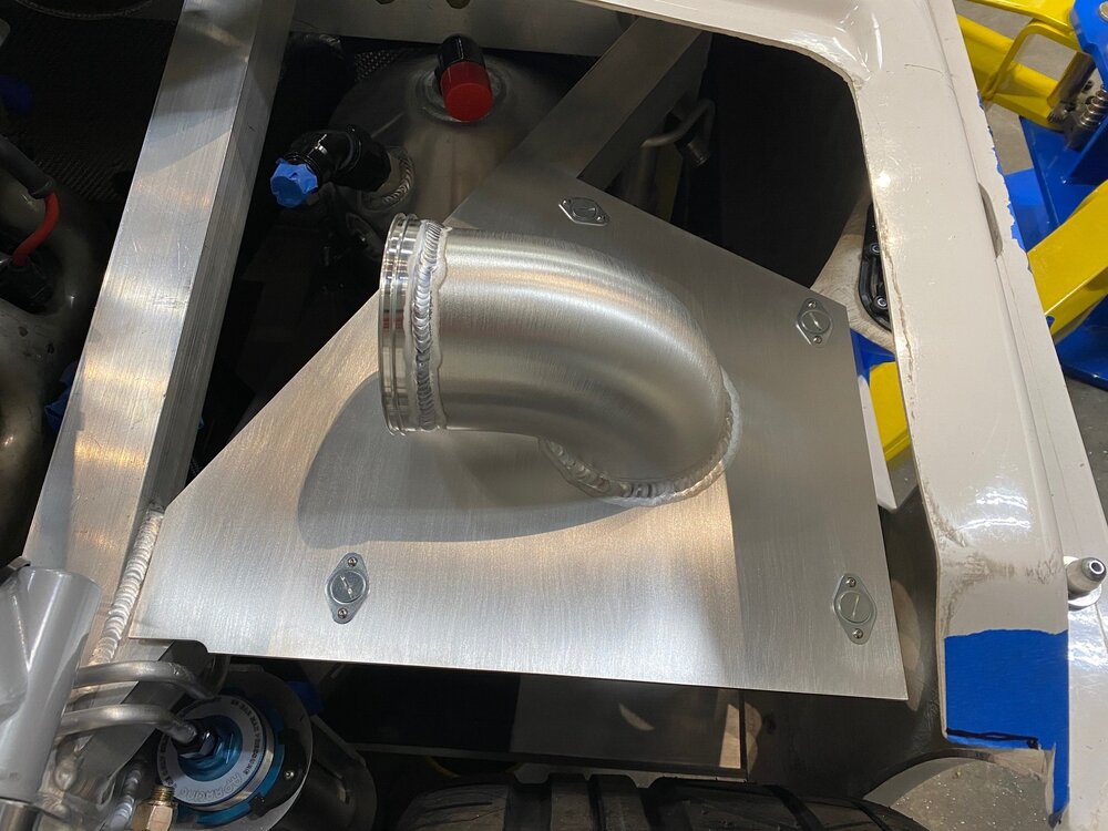
A bellmouth-style velocity stack was welded to the underside of the lid to reduce air turbulence. It also significantly stiffened the lid which kept it from warping when the 90-degree elbow was welded to the topside. The filter mounts directly to the velocity stack with a stainless steel clamp.

Velocity stack welded, upper elbow not welded yet and Dzus fasteners not installed yet
With the lid fastened via the Dzus connectors, a tight 90-degree elbow was positioned and tacked into place. The seam between the velocity stack and the elbow was welded on the inside and it was carefully ported. I defy you to find the seam in the picture below;-)

Velocity stack and elbow are ported; note that the screws for the Dzus connectors are flush
While not necessary, I had Abe weld the seam between the elbow and top because I didn’t want dirt getting stuck in seam. The picture below shows the finished lid with the Dezus fasteners tightened.
I’m not going to fabricate the actual box or the duct the connects the body to the air box at this point because I don’t need it for the first engine start. With both the source (filter) and the destination (throttle body) in place, it’s time to fabricate the induction tube and connect the two.
Underside of frame with Dzus springs installed
My plan is to fabricate aluminum closeout panels to dress up the engine compartment. With that in mind the lid for the cold air box is larger than it needed to be to cover the 2” x 2” chassis rail and to close the gap between cold air box and the wheel well liner. I used four Dzus fasteners to fasten the top to the frame.
Here’s how I got everything to line up perfectly. The placement of springs under the frame was tight so I flipped the frame upside down on the bench, located the springs and drilled a 1/8” hole at the center point of each spring. I then installed the frame on the chassis and clamped the lid in three places. Using the hole in the frame as a guide, I drilled upwards through the lid with a 1/8” bit and inserted a cleco to further clamp the lid to the frame. I repeated this for the remaining three holes. Now that the center hole for the Dzus connector was located, the left and right holes for the rivets needed to be drilled. To accomplish this, I fabricated a simple drill jig — three 1/8” holes, 1/2” apart in a straight line on a piece of scrap. I affixed the center hole of the jig to each hole in the frame with a cleco. After rotating the jig to the desired orientation (i.e. what would fit) I drilled the left hole with an 1/8” bit, inserted a cleco into that hole and drilled the right hole with the same bit. At this point, I had three perfectly spaced 1/8” holes, 1/2” apart in a straight line. The center hole was then enlarged with a 5/8” carbide hole cutter which had a 1/8” pilot so it was easy to get that part right. 1/8” flush rivets were used to affix the springs.
Left, center and right holes for Dzus connector
I repeated the process for the lid with four exceptions; (1) I used 4-40 screws rather than rivets because I didn’t want to drill clearance holes in the frame for the back of the rivets. The screws worked because the lid was 1/8” thick to prevent warping when welding, (2) the left and right holes were were drilled with a #43 bit and tapped, (3) the center hole was chamfered to get the Dzus connector to sit flat and (4) since there were no clearance issues the orientation was determined by what looked best rather than what would fit.
So that’s a total of 36 drilling operations. Screws or nutserts would have been a lot easier, but the convenience of the quarter-turn fasteners was worth the effort.
A bellmouth-style velocity stack was welded to the underside of the lid to reduce air turbulence. It also significantly stiffened the lid which kept it from warping when the 90-degree elbow was welded to the topside. The filter mounts directly to the velocity stack with a stainless steel clamp.
Velocity stack welded, upper elbow not welded yet and Dzus fasteners not installed yet
With the lid fastened via the Dzus connectors, a tight 90-degree elbow was positioned and tacked into place. The seam between the velocity stack and the elbow was welded on the inside and it was carefully ported. I defy you to find the seam in the picture below;-)
Velocity stack and elbow are ported; note that the screws for the Dzus connectors are flush
While not necessary, I had Abe weld the seam between the elbow and top because I didn’t want dirt getting stuck in seam. The picture below shows the finished lid with the Dezus fasteners tightened.
I’m not going to fabricate the actual box or the duct the connects the body to the air box at this point because I don’t need it for the first engine start. With both the source (filter) and the destination (throttle body) in place, it’s time to fabricate the induction tube and connect the two.
Scott
Lifetime Supporter
Thanks Del, version 2.0 came out a lot better...
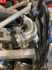
The space between the body and the chassis is tight and the prior induction tube put a small crack in the fiberglass. It’s difficult to figure out how much space you have with the body in place. However, when the body is removed the tail section sits too low. To solve this, I cut two temporary tubes to support the tail at the correct height which makes it easy to check clearance when the body is off. The vertical sharpie line spanning the temporary support and the chassis makes it easy to align the support and the rubber on top protects the fiberglass.

I was concerned that I’d need to scallop the 2” x 2” chassis tube or use an oval induction tube, but a 45-degree bend was all that it took… well, that’s only the case because we previously positioned the throttle body in the right place and used a tight-90-degree elbow on the cold air box lid.

I used a -64 AN (i.e., 4”) AdelWiggens tube connector to connect the elbow to the induction tube. These clamshell-style connectors have been used in aerospace for over 30 years. They can be opened and closed with a single hand and require no tools. They have some impressive specs, all overkill for an induction tube, but that’s how I roll LOL
The ferrules are typically butt welded, but I counterbored their IDs on a lathe to allow the them to fit over the tube. This ensured that they were perfectly concentric to the induction tube. Things were a bit sticky out-of the-box so I cleaned the grease off of the o-rings, ferrule grooves and sleeve and applied a thin layer of lithium grease.
Apparently the standard aerospace color for these types of clamps is purple, similar to the red/blue standard for AN fittings. I want to be 100% clear here. It’s purple and not any shade of pink!
The induction system is done other than the cold air box and the duct, neither of which are needed to start the engine.

The space between the body and the chassis is tight and the prior induction tube put a small crack in the fiberglass. It’s difficult to figure out how much space you have with the body in place. However, when the body is removed the tail section sits too low. To solve this, I cut two temporary tubes to support the tail at the correct height which makes it easy to check clearance when the body is off. The vertical sharpie line spanning the temporary support and the chassis makes it easy to align the support and the rubber on top protects the fiberglass.
I was concerned that I’d need to scallop the 2” x 2” chassis tube or use an oval induction tube, but a 45-degree bend was all that it took… well, that’s only the case because we previously positioned the throttle body in the right place and used a tight-90-degree elbow on the cold air box lid.
I used a -64 AN (i.e., 4”) AdelWiggens tube connector to connect the elbow to the induction tube. These clamshell-style connectors have been used in aerospace for over 30 years. They can be opened and closed with a single hand and require no tools. They have some impressive specs, all overkill for an induction tube, but that’s how I roll LOL
- Operating Pressure: 125 psig
- Proof Pressure: 250 psig
- Burst Pressure: 375 psig
- Axial Displacement: 0.250"
- Angular Misalignment: +/- 3.5 Degrees
The ferrules are typically butt welded, but I counterbored their IDs on a lathe to allow the them to fit over the tube. This ensured that they were perfectly concentric to the induction tube. Things were a bit sticky out-of the-box so I cleaned the grease off of the o-rings, ferrule grooves and sleeve and applied a thin layer of lithium grease.
Apparently the standard aerospace color for these types of clamps is purple, similar to the red/blue standard for AN fittings. I want to be 100% clear here. It’s purple and not any shade of pink!
The induction system is done other than the cold air box and the duct, neither of which are needed to start the engine.
Top notch workmanship and design Scott. Keep up the good work!
“50 shades of pink “, might make it look purple.
Scott
Lifetime Supporter
Brian, they certify that they only mixed blue and red LOL
I finally got around to mocking my EPAS, collapsible steering column and rack. The steering column doesn’t clear the pedals by much and I’d like to implement adjustable pedals which will raise them a bit. I should have taken measurements of the stock set up, but that’s impossible now because the original holes are welded shut! Can someone send me a couple of measurements so I can compare my floor-to-steering-shaft clearance with the stock set up? Basically, any A and B measurement at any convenient C and D distance from the front of the foot box would be helpful. Or one measurement and the angle of the steering shaft would also work. I think the stock steering column is D shaped, so I obviously would like the measurement with the max radius pointed down.

I finally got around to mocking my EPAS, collapsible steering column and rack. The steering column doesn’t clear the pedals by much and I’d like to implement adjustable pedals which will raise them a bit. I should have taken measurements of the stock set up, but that’s impossible now because the original holes are welded shut! Can someone send me a couple of measurements so I can compare my floor-to-steering-shaft clearance with the stock set up? Basically, any A and B measurement at any convenient C and D distance from the front of the foot box would be helpful. Or one measurement and the angle of the steering shaft would also work. I think the stock steering column is D shaped, so I obviously would like the measurement with the max radius pointed down.
Scott
Lifetime Supporter
In a previous post I mounted the intercooler pump with a 3D-printed bracket. I thought about converting the barbed outlet to an AN fitting, but the cap is plastic and I couldn’t come up with a reliable solution. Mega-priced supercars use silicon hose and hose clamps so I guess that it would be OK to use them in this one place LOL.
The intercooler pump outlet’s OD is 20 mm and the stainless steel tube running to the front of the is -10 (i.e., 5/8” or 15.9 mm). To resolve the mismatch a barbed adapter was machined on a lathe from a solid stainless steel rod. This adapter will be welded to the stainless steel hard line once the line is ceramic coated and the insulation sleeve is slid on.

The angle between the pump outlet and the stainless steel tube that runs down the side pod is 112 degrees. After lots of research the closest elbow I could find was a 19 mm ID, 120-degree silicon elbow.

The intercooler pump outlet’s OD is 20 mm and the stainless steel tube running to the front of the is -10 (i.e., 5/8” or 15.9 mm). To resolve the mismatch a barbed adapter was machined on a lathe from a solid stainless steel rod. This adapter will be welded to the stainless steel hard line once the line is ceramic coated and the insulation sleeve is slid on.
The angle between the pump outlet and the stainless steel tube that runs down the side pod is 112 degrees. After lots of research the closest elbow I could find was a 19 mm ID, 120-degree silicon elbow.
Scott
Lifetime Supporter
The lines in right side pod are finished. The approach is the same as the left side pod described here. There’s a lot less going on this side! The lines from top to bottom are:
- Air Jack (manifold to front jack, -6, aluminum)
- Heater Supply (engine outlet to heater, -10, aluminum)
- Heater Return (heater to pump inlet, -10, aluminum)
- Clutch (master cylinder to throwout bearing, 3/16”, stainless steel)
- Rear Brakes (residual pressure valve to brakes, 3/16”, stainless steel)
- Cooling Return (radiator to pump inlet, 1-1/2”, stainless steel)
While most of the clamps were 3D-printed , I used NotcHead Line Clamps in several locations. The hard line version requires a solid push on the line which results in a reassuring click.
Scott
Lifetime Supporter
Like some other builders, I decided to add a support arm to put the bellcrank in double shear. Agile Automotive went through several iterations on their endurance SL-Cs and they offer 4130 chromoly parts for their latest iteration:

I’ve found that the AUSTOR abrasive wheels shown below when loaded in a Dremel do a great job preparing irregular metal surfaces (a tube polisher is obviously the best tool for round tube). The kit below costs less than $15 and contains 60 wheels in multiple grits (e.g., 120, 180, 320, and 400).

As intended, the tube needed to be trimmed and each side was on/off the car several times to get fitment right. I placed a grade-8 washer between the tube nut and the billet upright.

Once they were installed the open barrel didn’t look finished and it would collect water and dust which might make its way into the bellcrank’s bearing. I designed and 3D printed a cap. The first version had a mundane flat top so I gave it a profile similar to the dimple dies elsewhere.

I also plan on welding a gusset between the 2” x 2” tube and the vertical billet member.
- 2x barrel welded to a cone (aka misalignment) washer
- 2x tube nut
- 2x bent and notched tube
I’ve found that the AUSTOR abrasive wheels shown below when loaded in a Dremel do a great job preparing irregular metal surfaces (a tube polisher is obviously the best tool for round tube). The kit below costs less than $15 and contains 60 wheels in multiple grits (e.g., 120, 180, 320, and 400).
As intended, the tube needed to be trimmed and each side was on/off the car several times to get fitment right. I placed a grade-8 washer between the tube nut and the billet upright.
Once they were installed the open barrel didn’t look finished and it would collect water and dust which might make its way into the bellcrank’s bearing. I designed and 3D printed a cap. The first version had a mundane flat top so I gave it a profile similar to the dimple dies elsewhere.
I also plan on welding a gusset between the 2” x 2” tube and the vertical billet member.
Del, give them a call and ask for Hill. He's the owner, a great guy and very SL-C and Aero knowledgeable.
Definitely will be doing, thanks for the info Scott!
Scott
Lifetime Supporter
I decided to use a remote electric water pump for the cooling system. I chose Pierburg, the same company that makes my intercooler pump. I initially purchased a CWA200 from Agile Automotive. They spec it on all of their SL-C and Aero builds and they’ve proven it at the 24-hour Thunderhill race and other endurance races. It allowed them to move the engine forward an inch or so and to relocate the pump’s weight to the nose box. Apparently the CWA200 has also been used by several GT2 teams. While the race credentials are nice to have, it’s been proven in many BMW and other OEM applications which is more applicable to my use case.
My engine builder expressed concerns about using an electric water pump. Seven or eight years ago he was retained by GM to test electric water pumps and he burned up a bunch of engines trying to find one that worked when a forced-induction, high-HP engine was pushed hard. Interestingly, the issue wasn’t flow rate. Rather the pumps didn’t create enough pressure to force steam pockets out of the rear of the block. This caused hot spots around the two rear cylinders (i.e., 7 and 8) which scorched their rings.
This need to have enough pressure to force steam pockets from the rear cylinders is why he advised me to leave the rear steam vent ports plugged. He strongly disagrees with the aftermarket steam vent kits that up-size the vent hose because they reduce pressure where you need it the most in an LS motor. Given that he’s been retained by GM for multiple R&D projects and he built the engines for the SL-C national champion after the team had a spate of blown engines from their prior marquee engine builder, it’s worth listening to him. That said, the tests were done a while ago.

To ensure that I would have enough pressure in the block, I upgraded the CWA200 to a CWA400 because its differential pressure rating is 1.9x higher (its flow is also ~40% higher). As can be seen in the comparison table, the CWA400 is marginally (i.e., ~1%) larger and while its max current rating is 2.2x it has an integral motor controller which is driven by a PWM signal. So, I gain ~2x increase in performance for a ~1% increase in size and a ~2x increase in power consumption (but only if I need it). Agile was also able to use the smaller pump on one of their other builds, so it only cost me the price delta and shipping. In the end, the upgrade was a no-brainier.

In the pictures below, the CWA200 is on the left and the CWA400 is on the right. The primary physical difference is that the mounting tabs are on opposites sides of the outlet (i.e., they are 180 degrees apart).


The cap on the CWA200 can be easily removed via four Torx screws, but it can’t be clocked. It took me a while to figure out how to remove the cap on the CWA400. It’s held in place by a split ring. To remove it, I used a large flat screwdriver to compress the ring between a bump on the body and a notch in the lid while twisting the screwdriver between the bump and the edge of the lid. It takes a couple of tries because an o-ring makes everything tight. When putting it back together you want to ensure that the split in the ring is 180 degrees (i.e., opposite) to the notch.

There’s a notch that’s machined in the edge of the lid which fits around the aforementioned bump. The sole purpose of the notch is to prevent the top from rotating and putting strain on the inlet and outlet hoses. The top can be easily clocked to any position by machining or filing a new notch.

Fortunately, the CWA400’s outlet orientation is perfect for my application and I didn’t need to make any modifications. The CWA200, whose cap can’t be clocked and is 180 degrees different, would have been a real pain in the ass to mount in my configuration. This was one of the other reasons why the upgrade made sense.
The next step is to mount the pump.
My engine builder expressed concerns about using an electric water pump. Seven or eight years ago he was retained by GM to test electric water pumps and he burned up a bunch of engines trying to find one that worked when a forced-induction, high-HP engine was pushed hard. Interestingly, the issue wasn’t flow rate. Rather the pumps didn’t create enough pressure to force steam pockets out of the rear of the block. This caused hot spots around the two rear cylinders (i.e., 7 and 8) which scorched their rings.
This need to have enough pressure to force steam pockets from the rear cylinders is why he advised me to leave the rear steam vent ports plugged. He strongly disagrees with the aftermarket steam vent kits that up-size the vent hose because they reduce pressure where you need it the most in an LS motor. Given that he’s been retained by GM for multiple R&D projects and he built the engines for the SL-C national champion after the team had a spate of blown engines from their prior marquee engine builder, it’s worth listening to him. That said, the tests were done a while ago.
To ensure that I would have enough pressure in the block, I upgraded the CWA200 to a CWA400 because its differential pressure rating is 1.9x higher (its flow is also ~40% higher). As can be seen in the comparison table, the CWA400 is marginally (i.e., ~1%) larger and while its max current rating is 2.2x it has an integral motor controller which is driven by a PWM signal. So, I gain ~2x increase in performance for a ~1% increase in size and a ~2x increase in power consumption (but only if I need it). Agile was also able to use the smaller pump on one of their other builds, so it only cost me the price delta and shipping. In the end, the upgrade was a no-brainier.
In the pictures below, the CWA200 is on the left and the CWA400 is on the right. The primary physical difference is that the mounting tabs are on opposites sides of the outlet (i.e., they are 180 degrees apart).
The cap on the CWA200 can be easily removed via four Torx screws, but it can’t be clocked. It took me a while to figure out how to remove the cap on the CWA400. It’s held in place by a split ring. To remove it, I used a large flat screwdriver to compress the ring between a bump on the body and a notch in the lid while twisting the screwdriver between the bump and the edge of the lid. It takes a couple of tries because an o-ring makes everything tight. When putting it back together you want to ensure that the split in the ring is 180 degrees (i.e., opposite) to the notch.
There’s a notch that’s machined in the edge of the lid which fits around the aforementioned bump. The sole purpose of the notch is to prevent the top from rotating and putting strain on the inlet and outlet hoses. The top can be easily clocked to any position by machining or filing a new notch.
Fortunately, the CWA400’s outlet orientation is perfect for my application and I didn’t need to make any modifications. The CWA200, whose cap can’t be clocked and is 180 degrees different, would have been a real pain in the ass to mount in my configuration. This was one of the other reasons why the upgrade made sense.
The next step is to mount the pump.
Scott
Lifetime Supporter
The cooling pump bracket was made from 3/16” aluminum plate and 1/8” right-angle aluminum. Two of the pump’s mounting flanges are offset, so aluminum spacers were machined on a lathe. I had Abe weld them to the bracket because that reduces the number of things that I can lose by two;-) The bottom two holes are mounted through the 2” x 2” chassis tube with long M8 screws. The top screw is an M8 into a rivnut located in the top of the chassis tube.


As can be seen below the pump is slammed to the bottom of the car. This provides the inlet with the maximum amount of gravity feed from the radiator, keeps it’s center of gravity as low as possible and it allows the outlet to clear the cold air box.

The next step is to fabricate the inlet and outlet
As can be seen below the pump is slammed to the bottom of the car. This provides the inlet with the maximum amount of gravity feed from the radiator, keeps it’s center of gravity as low as possible and it allows the outlet to clear the cold air box.
The next step is to fabricate the inlet and outlet
Scott
Lifetime Supporter
I didn’t want to use the cooling pump’s barbed inlet or outlet. Fortunately, the cap is removable and made of aluminum so I cut the barbs off. A Y-shaped outlet was made from a 1-1/4” and two 3/4” tubes. The junction of the Y was slot shaped and a mandrel mounted in a hydraulic press was used to bend it round so that it would match the larger tube.

Two -12 ORB weld bungs were shortened on a lathe and a shoulder was machined to keep everything concentric during welding. In the picture below, the top bung is stock and the two at the bottom have been modified.

The Y was welded directly to the pump’s cap to keep packaging compact and to reduce the number of connections that might leak. The cap was replaced and the pump was mounted to check the outlet and to mock the inlet. When we tried to remove the cap to weld the inlet we couldn’t get it off.
Do’h #^#%#$! I had it on and off at least five times, but no matter what we tried we couldn’t remove it. It was late and with removal attempts quickly escalating, I decided that for the cap’s safety we should resign our efforts for the day. Abe was able to remove it in the morning. We’re not sure what the issue was, so we put some grease on the o-ring and compressed the split ring a couple of times.
The inlet uses a 1-1/2” tube for the radiator return and a 1” tube for the heater return. The heater line uses a standard AN fitting and the remaining three lines use clamshell couplers.
All of the weld bungs are female because if the cap were dropped the threads on a male bung might get damaged and wreck the entire part. This allows damaged male threads to be tossed and easily replaced. This “disposable male genitalia” approach is endorsed by the #MeToo Movement. External plumbing does have disadvantages!
A lot of effort went into the cap. If I need to replace the pump, I can simply swap the caps — assuming I can remove it LOL.


Two -12 ORB weld bungs were shortened on a lathe and a shoulder was machined to keep everything concentric during welding. In the picture below, the top bung is stock and the two at the bottom have been modified.
The Y was welded directly to the pump’s cap to keep packaging compact and to reduce the number of connections that might leak. The cap was replaced and the pump was mounted to check the outlet and to mock the inlet. When we tried to remove the cap to weld the inlet we couldn’t get it off.
Do’h #^#%#$! I had it on and off at least five times, but no matter what we tried we couldn’t remove it. It was late and with removal attempts quickly escalating, I decided that for the cap’s safety we should resign our efforts for the day. Abe was able to remove it in the morning. We’re not sure what the issue was, so we put some grease on the o-ring and compressed the split ring a couple of times.
The inlet uses a 1-1/2” tube for the radiator return and a 1” tube for the heater return. The heater line uses a standard AN fitting and the remaining three lines use clamshell couplers.
All of the weld bungs are female because if the cap were dropped the threads on a male bung might get damaged and wreck the entire part. This allows damaged male threads to be tossed and easily replaced. This “disposable male genitalia” approach is endorsed by the #MeToo Movement. External plumbing does have disadvantages!
A lot of effort went into the cap. If I need to replace the pump, I can simply swap the caps — assuming I can remove it LOL.
Similar threads
- Replies
- 10
- Views
- 10K
- Replies
- 4
- Views
- 5K