Ken Roberts
Supporter
Keep in mind that the springs Scott mentions are sized for the Penske struts and not the standard QA1s.Thanks Scott for taking the time to measure them. Looks like I'm going with a set of Eibachs.

Keep in mind that the springs Scott mentions are sized for the Penske struts and not the standard QA1s.Thanks Scott for taking the time to measure them. Looks like I'm going with a set of Eibachs.
How did you guys keep it so clean and free of alpha case when welding?
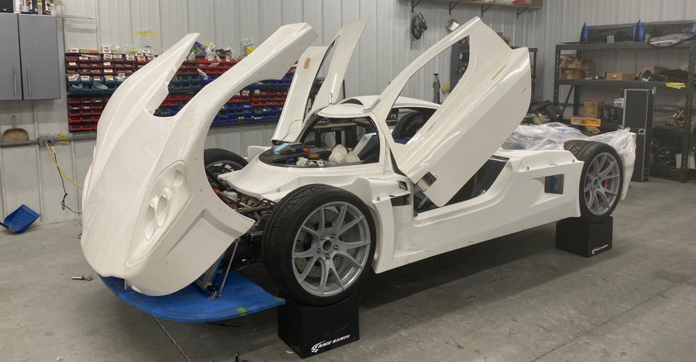
I hauled my car down to Allen’s and we installed the door actuators and brackets discussed in a previous post. The electric door actuators have several advantages. Besides the cool factor, they apply tension to the door ensuring that it’s firmly seated on the door seals, they keep the door from rattling, they remove the need for a door handle resulting in a clean exterior and they provide a locking mechanism.
However, if there’s a failure they could potentially lock you into or out of your car. One builder had an electrical failure while driving on the highway. He was stuck on the shoulder, baking in the summer sun with the door locked shut. Fortunately, he had his phone and the foresight to build an external harness with a portable battery to power the door open (although his use case was him locked out rather than in.) He called his wife and by the time she arrived to free him he was cooked medium rare.
While that story ended well, a Texas man and his dog died in the parking lot of a waffle house after becoming trapped in a 2007 Corvette. Apparently, an electrical system failure prevented the electric locks and horn from working. Unbeknownst to the owner, there is a manual release lever between the driver’s seat and the door (article here). IMO it’s extremely important to have an emergency release.
I have seen multiple pictures of SL-C’s with pull-pin-based door releases for the actuators, but to my knowledge none of them work. The issue is that the actuator applies about ??? pounds of tension when the door is closed. The good news is that Peter, who built the first SL-C with electric doors, has been working with a mechanical engineer to develop a reliable release mechanism. As can be seen in the video below, Allan and I tested it. It is well engineered and it worked great.
Note that the cutouts in the door and spider are related to my body mods and have nothing to do with the actuators and release mechanism. That said, having installed many doors and actuators, Allan was interested to see what happens inside the door. in addition, I measured the tension to be about 90 pounds and not the 160 pounds that I mentioned in video.
I’m talking with Peter about a couple of enhancements and a potential group buy.
My plan is to mount a red T-handle with a “DOOR RELEASE” label on it to the side of the footwell immediately forward of the door. It will look race and no way is someone going to miss it. I will also run a wire from each door into the nose so that I can open the doors if I get locked out. I don’t see that as a security risk because a would-be thief would need to know where the wires were and have a pair of pliers. In addition, my steering wheel is removeable and they would need a Krontec quick disconnect and know what my proprietary CAN bus message is to start the car.
If anyone knows where to get a red T-Handle that can be laser etched, let me know
Scott - I have been worried about this as well. Fran is about to start my build in his shop and will be installing Allen’s Door actuators. So count me in for the “group buy”. Do you know how soon we can get them?I hauled my car down to Allen’s and we installed the door actuators and brackets discussed in a previous post. The electric door actuators have several advantages. Besides the cool factor, they apply tension to the door ensuring that it’s firmly seated on the door seals, they keep the door from rattling, they remove the need for a door handle resulting in a clean exterior and they provide a locking mechanism.
However, if there’s a failure they could potentially lock you into or out of your car. One builder had an electrical failure while driving on the highway. He was stuck on the shoulder, baking in the summer sun with the door locked shut. Fortunately, he had his phone and the foresight to build an external harness with a portable battery to power the door open (although his use case was him locked out rather than in.) He called his wife and by the time she arrived to free him he was cooked medium rare.
While that story ended well, a Texas man and his dog died in the parking lot of a waffle house after becoming trapped in a 2007 Corvette. Apparently, an electrical system failure prevented the electric locks and horn from working. Unbeknownst to the owner, there is a manual release lever between the driver’s seat and the door (article here). IMO it’s extremely important to have an emergency release.
I have seen multiple pictures of SL-C’s with pull-pin-based door releases for the actuators, but to my knowledge none of them work. The issue is that the actuator applies about ??? pounds of tension when the door is closed. The good news is that Peter, who built the first SL-C with electric doors, has been working with a mechanical engineer to develop a reliable release mechanism. As can be seen in the video below, Allan and I tested it. It is well engineered and it worked great.
Note that the cutouts in the door and spider are related to my body mods and have nothing to do with the actuators and release mechanism. That said, having installed many doors and actuators, Allan was interested to see what happens inside the door. in addition, I measured the tension to be about 90 pounds and not the 160 pounds that I mentioned in video.
I’m talking with Peter about a couple of enhancements and a potential group buy.
My plan is to mount a red T-handle with a “DOOR RELEASE” label on it to the side of the footwell immediately forward of the door. It will look race and no way is someone going to miss it. I will also run a wire from each door into the nose so that I can open the doors if I get locked out. I don’t see that as a security risk because a would-be thief would need to know where the wires were and have a pair of pliers. In addition, my steering wheel is removeable and they would need a Krontec quick disconnect and know what my proprietary CAN bus message is to start the car.
If anyone knows where to get a red T-Handle that can be laser etched, let me know
This red one looks pretty coolWell executed.
Aluminum dipstick handles are inexpensive and can be etched, cable easily attached, and come in all sorts of shapes/sizes.