Southern GT #48

Ed McClements

Supporter
Attacked a large sheet of 3mm steel with angle grinder and slitting disc, then used a Bosch hole saw to cut..err...holes for the master cylinders. The hole saw complained a bit, but I took it slow and used plenty of cutting fluid.


48738526517_0d72335e8e_o.jpg

48738341581_12b4553b66_o.jpg

48738017163_990a0abd96_o.jpg


The master cylinder mounting plate will be triangulated front and rear to take the weight of a size 9 firmly planted on the brake pedal. I've yet to make the tabs at the sides which will bolt the pedal box down to the ally brackets (which will be fixed to the chassis). Throttle yet to be finalised, but will probably incorporate some adjustment of ratio (quick throttle / slow throttle) and also some adjustment of travel. Clutch pedal will have a stop, so that I don't blow-out the piston on the slave cylinder.
 

Neil

Supporter
Eddy;

Nice work. I'd attach a small right-angle "lip" on the top edge of the MC panel. This will provide additional stiffness so that the panel does not bow forward under heavy pedal pressure.
 

Ed McClements

Supporter
Eddy;

Nice work. I'd attach a small right-angle "lip" on the top edge of the MC panel. This will provide additional stiffness so that the panel does not bow forward under heavy pedal pressure.
Great minds think alike, Neil....the reason for the flat section at the top of that piece is in readiness for exactly that construction. All should become clear later this week, when I get some more 'shop time.
 

Ed McClements

Supporter
Added the aforementioned "lip", bracing front and rear, pivot bar for the pedals and so on. Made up a trial throttle pedal, but have yet to add the linkage. How much throttle cable travel do I need in order to operate a Edelbrock 1406 or equivalent 650cfm Holley?

48809258993_b8ec61f80e_o.jpg


48809255658_c9d690bcf5_o.jpg


48809751507_7dde4e641c_o.jpg


48809256568_b75ebf3dbd_o.jpg
 

Ed McClements

Supporter
Linkage for throttle cable - several positions available for the rose-jointed bar which give a variation from slow to quick action.


48842856986_6b34c02282_o.jpg


48842489188_9e69945734_o.jpg


48842489928_01aefedde4_o.jpg


There's a throttle stop for the "at rest" position; will add one for WOT, too. The threaded thingamajig with the two nuts is the cable adjuster, to remove any slack from the throttle cable.
 

Ed McClements

Supporter
Finished

48895730808_3153ce62d5_o.jpg

48895730203_f51dbfb580_o.jpg

48896455117_650742a645_o.jpg

48896262931_dddd2ba77a_o.jpg

48896452472_ff767798de_o.jpg

48895733208_48459e60b1_o.jpg


Note the following items:-
Careful application of bird droppings in place of actual MIG welds
One of the black anodised clevises on the brake balance bar had a sloppy fit as delivered, causing an annoying amount of play on the brake pedal, so I made a replacement clevis (the non-anodised one in the pics)
Mounting rails are bolted to chassis/floor with 6 x M8 high tensile bolts; pedal box is mounted to rails with 6 x M8 bolts. Should withstand one of those "oh sh1t!" moments OK.
 

Ian Anderson

Lifetime Supporter
Hi
When you brake one of the circuits will flow more fluid than the other so the balacne bar will swivel.

My eye would see that the clevis is too close to the brake pedal part to allow the pivot bar to swivel.

Ian
 

Ed McClements

Supporter
Hi
When you brake one of the circuits will flow more fluid than the other so the balacne bar will swivel.

My eye would see that the clevis is too close to the brake pedal part to allow the pivot bar to swivel.

Ian
Hi Ian
Thanks for your comments. The pedal box has been quickly assembled for the photos, though in fact the balance bar has enough travel to pivot until it eventually contacts the balance bar tube...in both directions. It's also my plan to move both clevises (clevii?) outward slightly, and insert a large-diameter washer between each clevis and the balance bar tube, as I have always understood this to be the safest solution, preventing either clevis from getting hung up on the tube.
Similar to these units from Tilton, Wilwood and Unknown:-

jamar-performance-dual-master-cylinder-brake-pedal-balance-bar-replaces-tilton-racing-72-250-wilwood-340-1757-cnc1214-cnc1215.jpg

wilwood-bias-braking-pedal-balance-bar-343-p.jpg

balance_bar_short_small.jpg
 

Ian Anderson

Lifetime Supporter
Hi Ian
Thanks for your comments. The pedal box has been quickly assembled for the photos, though in fact the balance bar has enough travel to pivot until it eventually contacts the balance bar tube...in both directions. It's also my plan to move both clevises (clevii?) outward slightly, and insert a large-diameter washer between each clevis and the balance bar tube, as I have always understood this to be the safest solution, preventing either clevis from getting hung up on the tube.
Similar to these units from Tilton, Wilwood and Unknown:-

jamar-performance-dual-master-cylinder-brake-pedal-balance-bar-replaces-tilton-racing-72-250-wilwood-340-1757-cnc1214-cnc1215.jpg

wilwood-bias-braking-pedal-balance-bar-343-p.jpg

balance_bar_short_small.jpg
Great stuff

Looks like you have it all in hand

Ian
 

Ed McClements

Supporter
There wasn't sufficient clearance between the brake and throttle pedal, and I didn't really like the look of the Mk1 pedal, so I had another crack at it...

49232936817_d5c6de386f_o.jpg
49232712816_e16c7c7fba_o.jpg
The odd dogleg near the bottom is to provide clearance for the brake bias bar.

In order to finalise the position of the pedals, and relationship between pedals / steering / gearshift I needed to work on the seating position. I want to sit low in the car, I don't want an arms-outstretched position, I want the gear lever to fall naturally under the hand etc etc. So, I mocked-up a seat from an old packing-case....

49286644823_051f2073eb_o.jpg
49287350632_abe02a997e_o.jpg

I have no experience with composites, and I want to sort of replicate the look and feel of the real thing, or at the very least a late-60s sports racing GT car.
11482.jpeg
308.jpg

this-ford-gt40-replica-was-born-to-tear-

So, steel tube and an old pipe bender it is.

49286644878_1033b2b026_o.jpg
49286663313_6859eecd72_o.jpg
49287141831_b8c05212da_o.jpg
49310329193_671ec5c8ff_o.jpg
49310329198_3ae7308b62_o.jpg

I'm a bit further forward than this; have started adding brackets and supports for the actual seating, but no pics yet.

I plan to mount the seats using machined U-brackets to retain the full-width round tube at the front lower part of the seat, and a couple of bolts through tabs welded to the backrest which will screw into the bulkhead. That way, it should be possible to remove the two bulkhead fixings, and slide the seat back out of the front retaining brackets, then lift the seat out of the car. This is intended to simplify access to the removable bulkhead panel.

Thing is, none of this can be entirely finalised until I have built the engine and selected a water pump / pulley arrangement so that I know if a bulkhead bulge will be needed.
 

Neil

Supporter
Eddy, you might consider fastening your seats into the car with ball lock pins. It will make the installation and removal far quicker and easier than using bolts. Also, no tools would be required to pull the seats out. Use them in shear with your u-brackets.
 

Attachments

  • balllock pin.jpg
    balllock pin.jpg
    3 KB · Views: 383

Ed McClements

Supporter
Eddy, you might consider fastening your seats into the car with ball lock pins. It will make the installation and removal far quicker and easier than using bolts. Also, no tools would be required to pull the seats out. Use them in shear with your u-brackets.

Top tip...thanks, Neil.

Have mocked-up seat base & back with ply....to be replaced with 2mm aluminium sheet (suitably swaged for stiffness) when seat layout finalised.

The seat is just sitting on the sill here...

49347474446_16ebacf006_o.jpg


49347012278_0a9a9b7d38_o.jpg


And obvs in the correct place here...

49347682792_2e2d157c4d_o.jpg


With the 5/8" seat frame, a slim seat base and just sufficient padding I should be able to keep the seating position low and retain decent headroom (not for me, you understand...at 5'9" I'll be OK whatever). Even in its current form, the driving position feels really good - legs comfortable, arms relaxed, plenty of elbow room.
 

Ed McClements

Supporter
A pair of front uprights have arrived in the post...

49434316458_669fb9259c_o.jpg


49435011267_11d4bc8aae_o.jpg


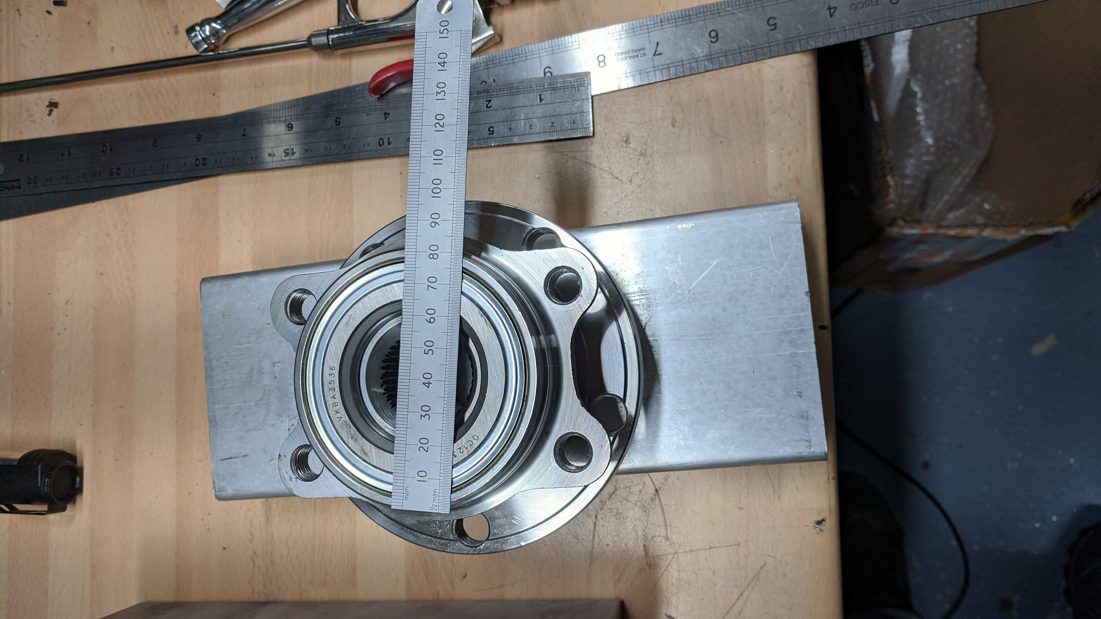
But they're hidden somewhere within these two large blocks of aluminium, and I need to dig them out. That's a rear hub/bearing assembly in the picture (you can see the drive splines), so I'll be using one of these....

91wbMM8msfL._SL1500_.jpg


....on the front uprights, and fabricating steel uprights for the rear. Both hub assemblies are Audi / VAG 5 x 112 PCD units, which give a wide choice of brake diameters and offsets with a 68mm centreing hole. Mercedes uses the same PCD (though with a 67mm centreing hole) which opens up the option of 295mm x 30mm discs with an integral bell:-

h-preview.jpg

b79c30fe-45f7-4dfe-9336-c79ad0329761.jpg


which ought to fit inside a 15" rim. Failing that, there are several VAG 288mm discs, though none with such a large bell.

The plan for the front uprights is to mimic the geometry of the John Wisher uprights, because the SGT susp mounts and wishbone lengths are designed for these components. It would be much simpler just to buy a set of the cast uprights, but they're over £1k per corner and there just isn't that much in the budget. I know that @Jim C built some ally uprights for his RF105, and @blueovalz built some for his Manta, and the plan is for something like that. I plan to bore the bottom of the upright to take a steel sleeve with the correct taper for bottom balljoint, and mill out a pocket above that to get to the balljoint nut. Somewhere in the centre of the upright I'll machine out an 80mm x 18mm circular recess to take the back of the hub/bearing assembly, and have this as a close fit to take the susp loads into the uprights, and not rely on the 4 x mounting bolts. At the top, there'll be a bolted-on assembly for the upper balljoint, and the plan is to have it bolted to the inner part of the upright...

lotus_front_upright.jpg


5022757_orig.jpg


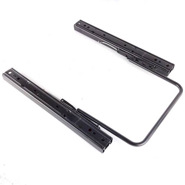
so that if necessary I can shim between the top mount and the upright, giving me camber adjustment which is independent from SAI/KPI (or vice-versa). I think it should be possible to integrate the steering arm into the top balljoint mount, like the second picture. Caliper mounts? Not sure yet.

So....what are the dimensions of the John Wisher uprights? Somewhere between 200mm and 220mm between top and bottom balljoints, with 8 to 10 degrees of SAI?


49435011292_7aae8b7c5f_o.jpg
 
Last edited:
Back
Top