Toms RCR 40 Trackracer

Status
Not open for further replies.

Randy V

Moderator-Admin
Staff member
Admin
Lifetime Supporter
Kalun - The side-cable is not to it's full limit but close... You should have seen it **before** I re-engineered most of the transmission side of the system.. Actually you can see it on my build-site..

Tom - Superb work! I had also anticipated creating filler plates to go in front of the roll-bar forward hoop / A-Pillars..
 
Randy,

I put it as much forward as possible, this way the front lip is tucked right underneath the spider windscreen frame with a nice even gap. A foam rubber underneath and the correct weatherstripping on the top lip, will clamp the dashboard nicely in between the spider and the chassis. This way it is well isolated and dampened to avoid resonance sounds.

This is a shot of the front of the a pillar of the cage. The dashboard cuts into the lines of the front roll hoop in my case.
PICT2973.jpg

So no way to fit a plate there to cover it, without destroying the lines. The dashboard also follows nicely the lines of the inner doorliner. When the door is closed you don´t see it anyway and once the gaps has been perfected and painted all satin black it will look great.

My Car ( purchased second hand) didn´t come with the RCR dashboard. Integrated was a lightweight version by some other source which was very flimsy. So i reeinforced it with two additional layers of 350g glass on the backside and the mounting tabs. Therefore the sanding and resin tracks on the mounting tabs are resulting from this.

TOM
 
Last edited:
Functional fresh air naca inlets

Hi

I worked on building the duct system for a functional fresh air supply.
My intenition is was to have it permanently installed in the front clip and connected to the mono like on the original cars. So the concept is the same, the design is different, lets say very functional :thumbsup:

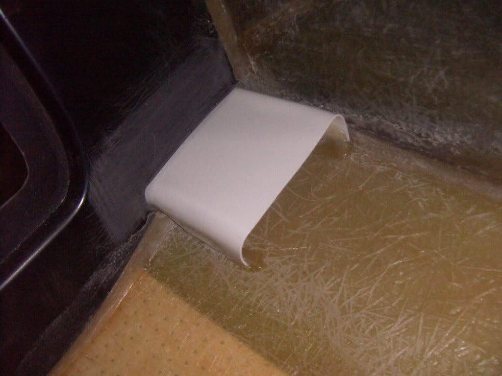
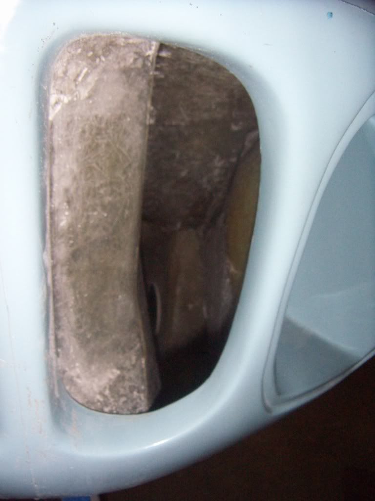
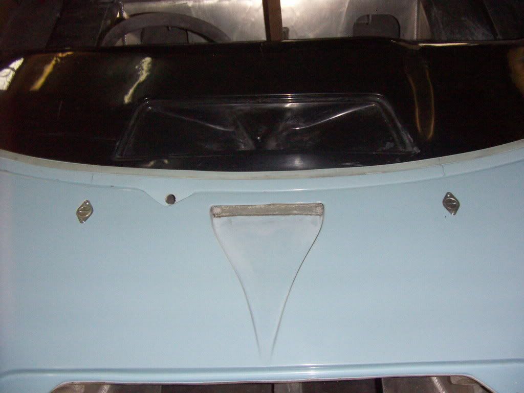
First i extended the naca inlet through the inner liner of the clip. Made a simple positive out of 1,2 mm PP foil ( easy to bend by termoforming)and fixed it with hot melt glue.

PICT2988.jpg


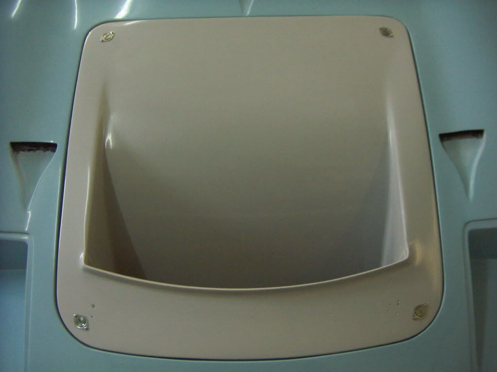
This was covered by some layers of 350 g glass.
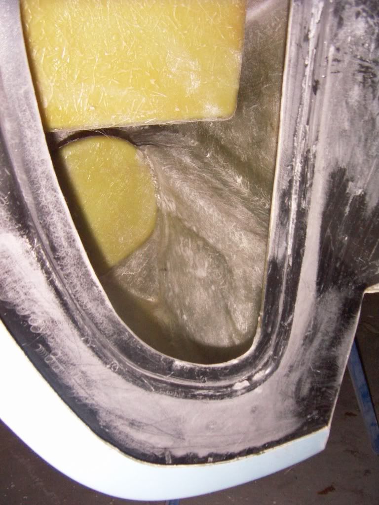
inlet after cleaning the edges.
PICT2989.jpg


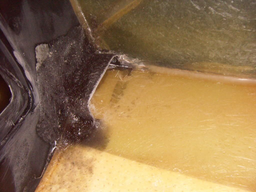
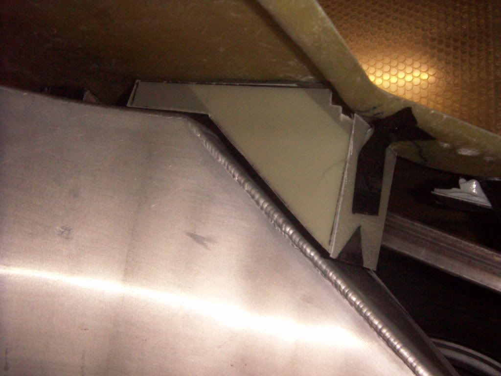
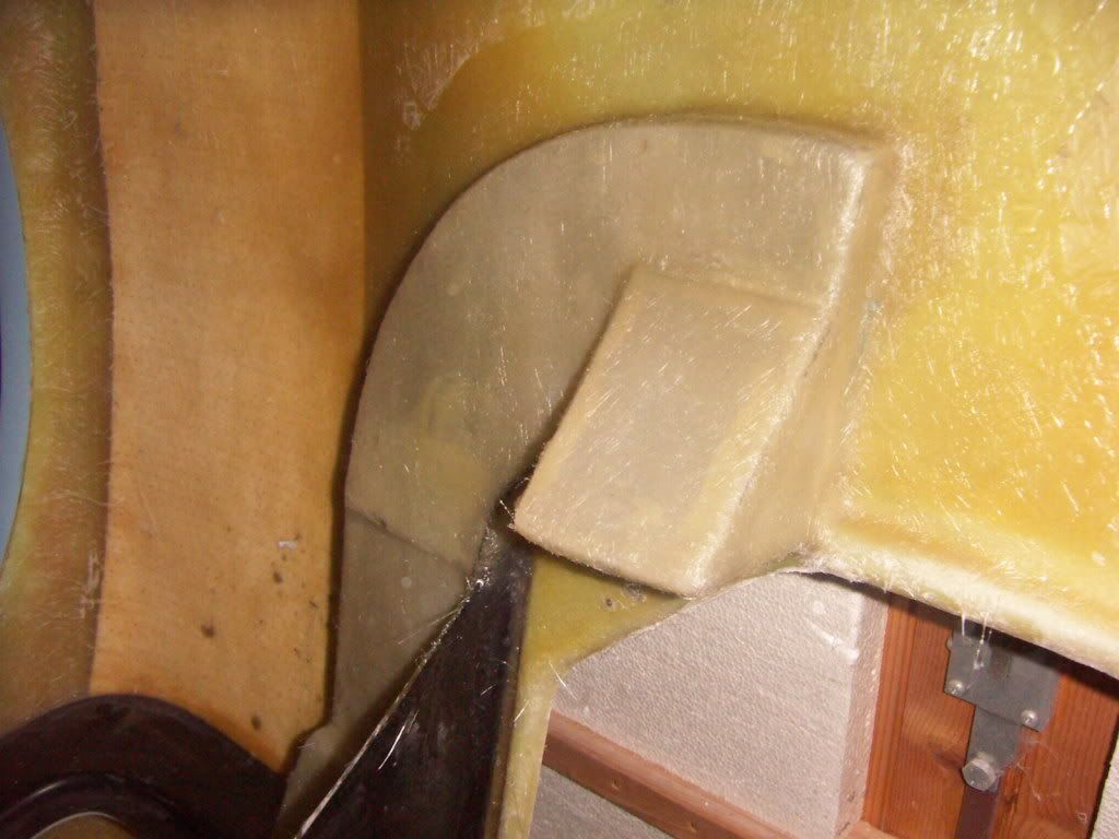
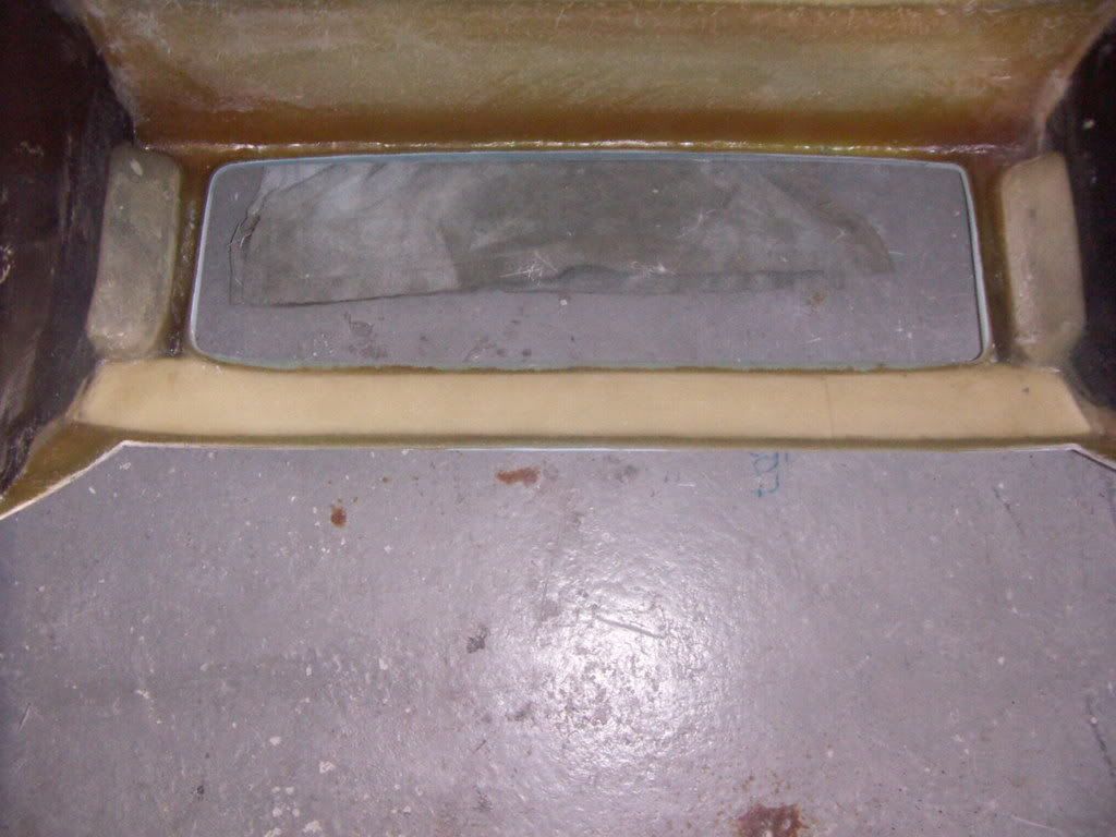
in order to avoid water coming in when driving in rain i build a "watertrap". The incoming air is hitting a vertical wall first and has to go around it and hitting a second wall before entering the further duct. The housing has a steep angle for collecting and leading away the water.

Water trap
PICT2990.jpg

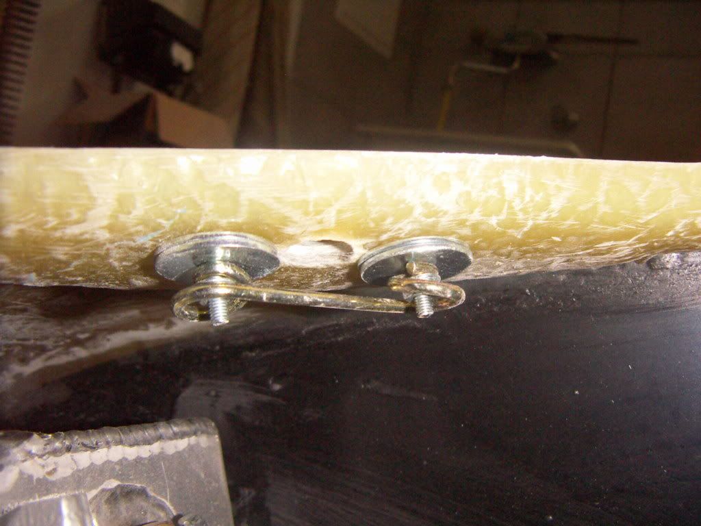
I build this and the rest of the ducting out of a finished 1,5mm glassfiber plate, which i glued together with 2k epoxy glue.

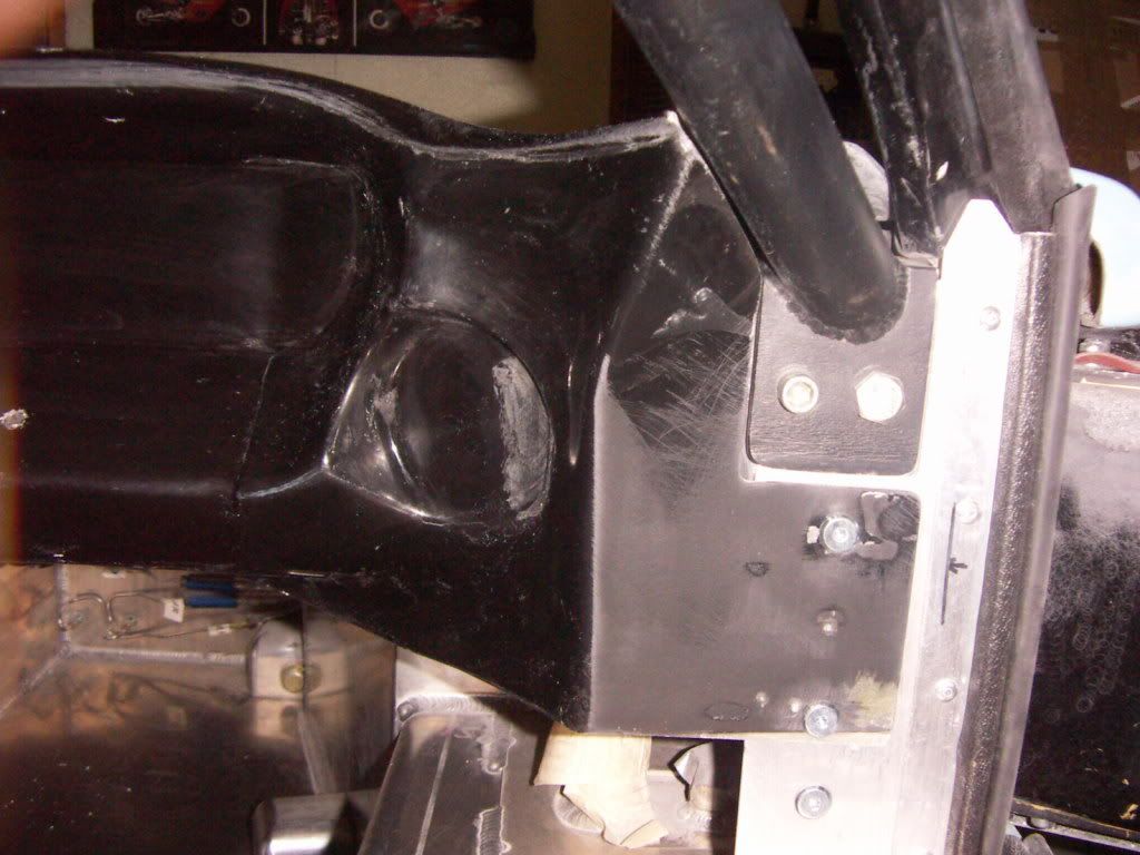
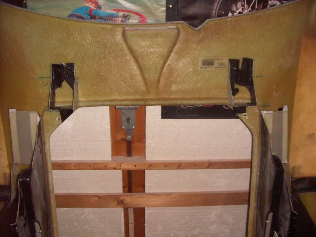
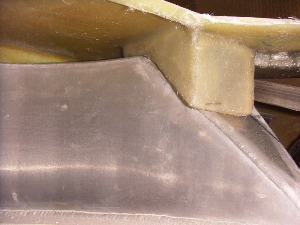
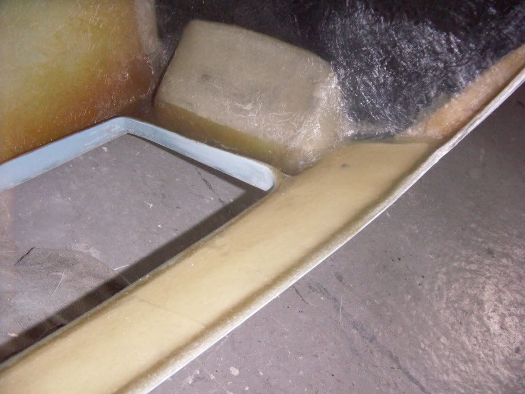
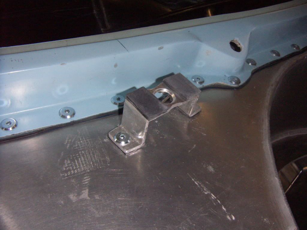
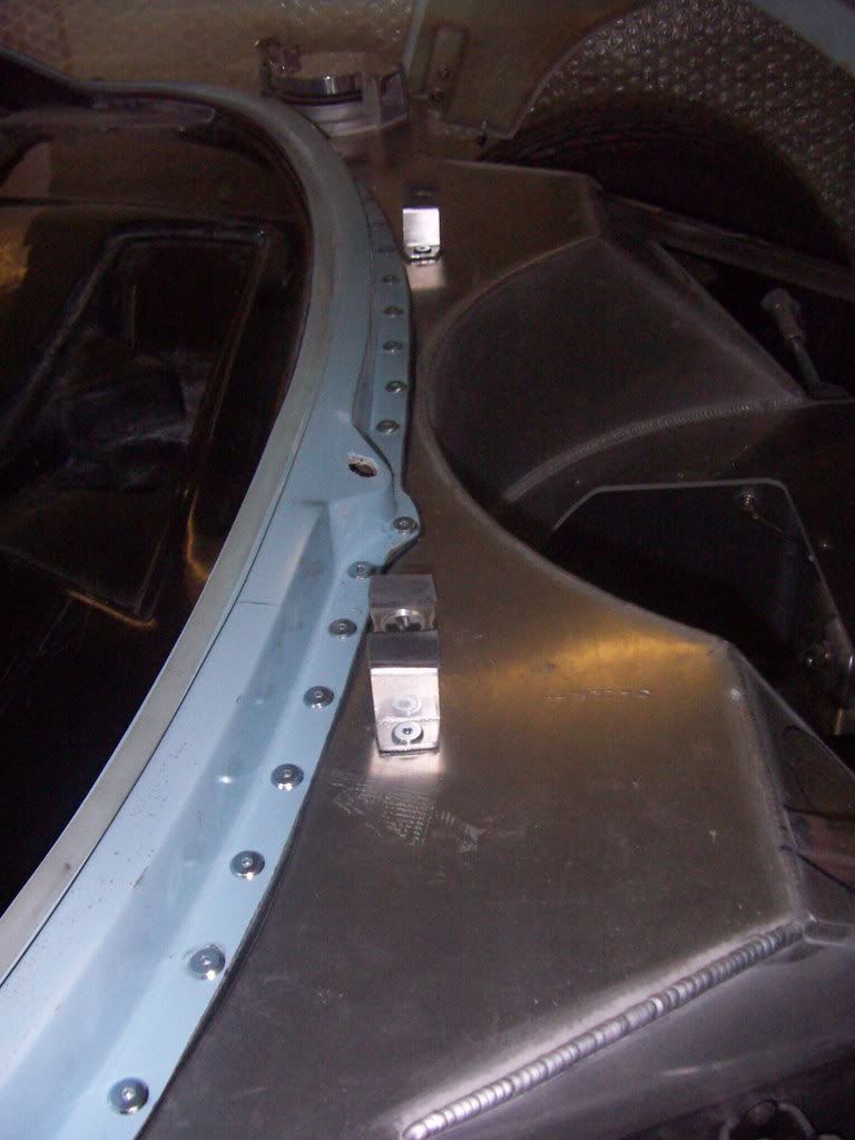
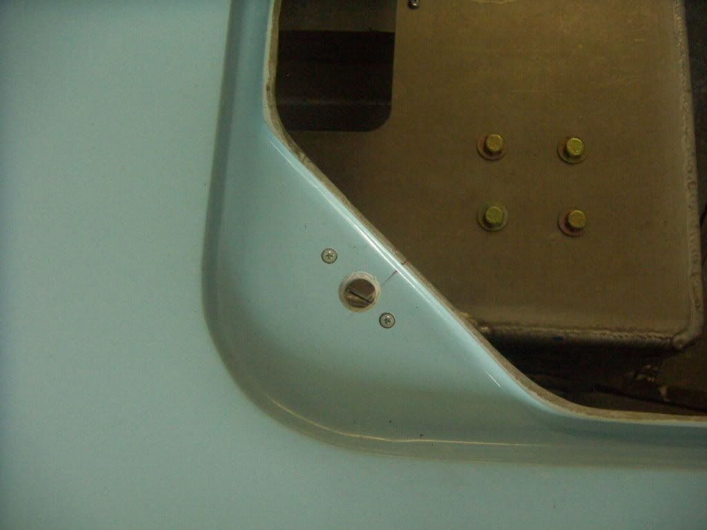
Next step was to build the connection housings to the mono. I didn´t bother to try to measure the angle and built it just right there with the clip mounted ( has been pretty tight sitting in there :laugh:).
I left a 5mm gap to the chassis and 8mm to my front frame to have no issues with fitting the front clip.
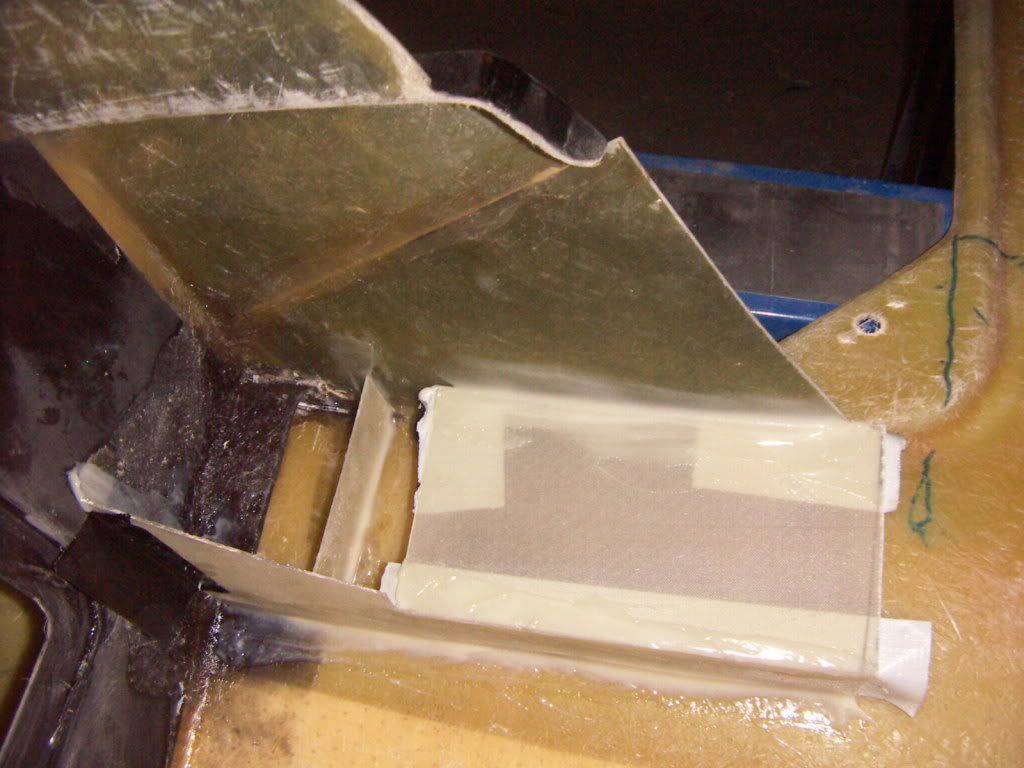
rough mock up
PICT2992.jpg

connection boxes fixed with tank tape
PICT2995.jpg


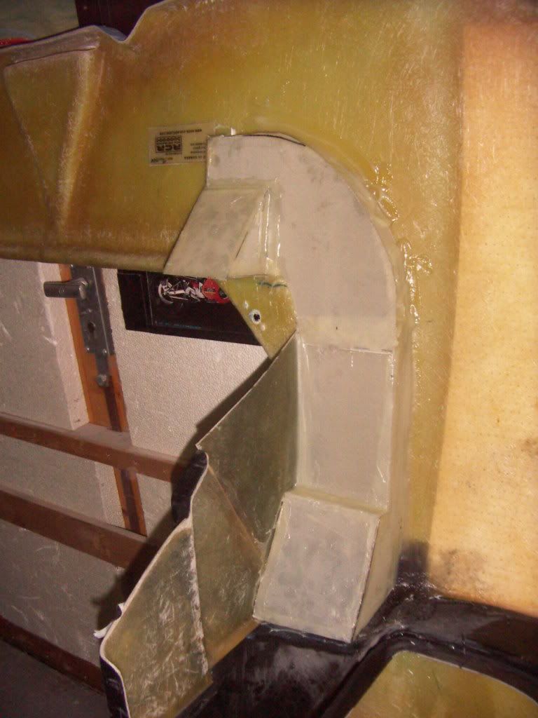
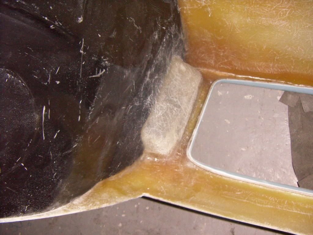
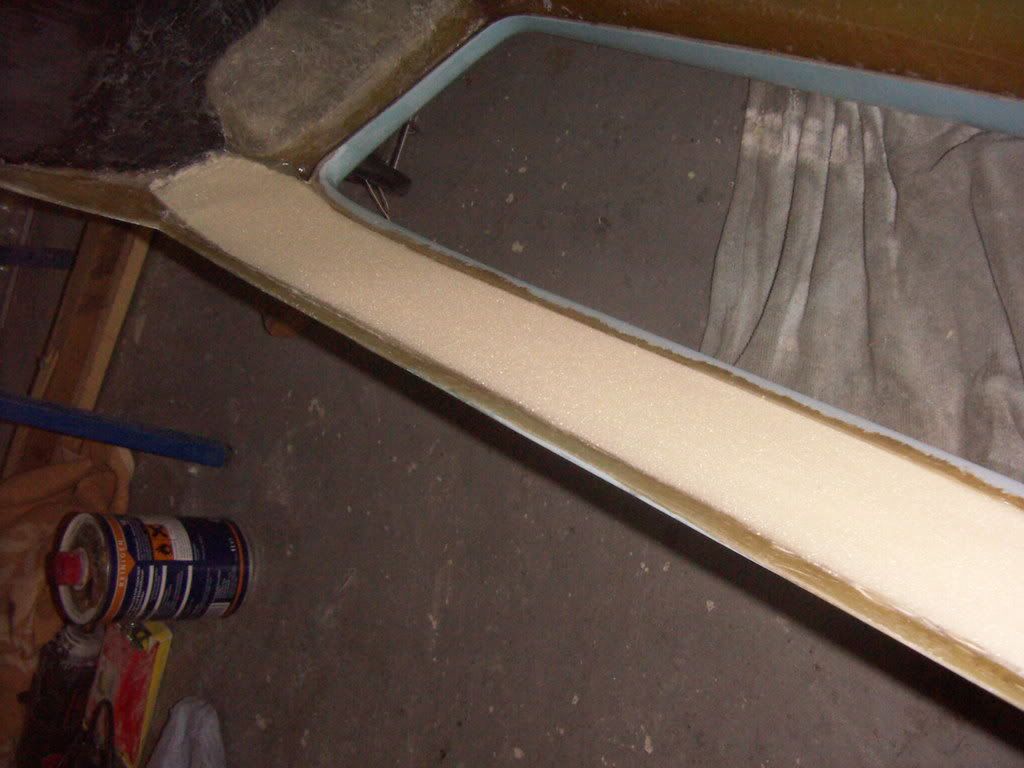
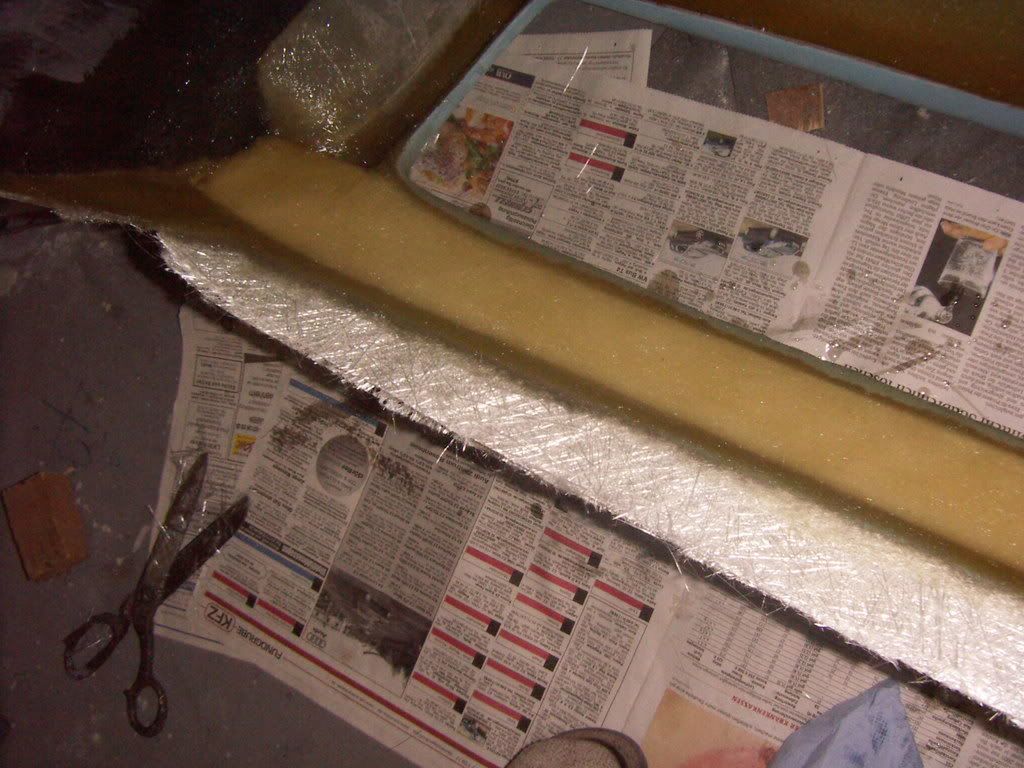
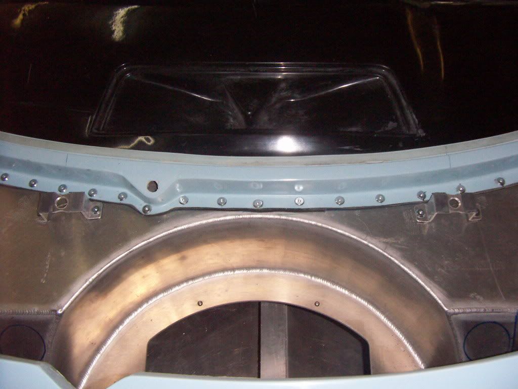
than i connected them together with the water trap by building the rest of the duct.
PICT3000.jpg

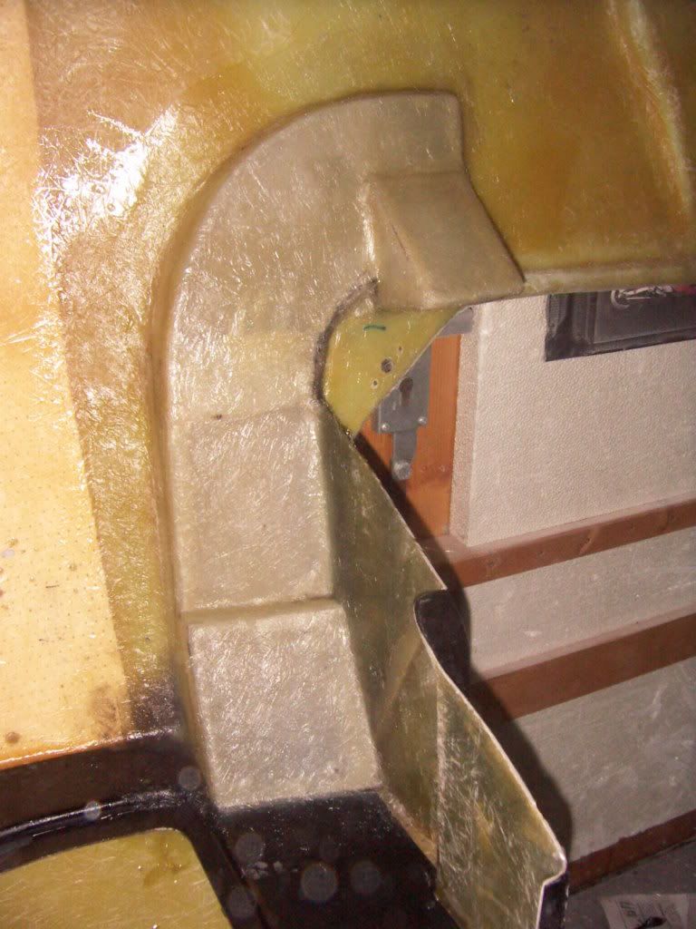
All of this was than covered with 2 layers of 350 g glass to fix it permanently to the clip.
PICT3004.jpg


PICT3006.jpg


it fits nicely to the chassis, there is still a 3mm gap all around which will be than filled with rubber foam to seal it ( like on the originals).
PICT3008.jpg


THe watertrap will receive a service opening out of aluminum to have a possibility to clean it.


Thanks
TOM

awh: 330 h
 
Last edited:

Chris Kouba

Supporter
Hey!!! That too looks vaguely familiar- and very nice execution on it as well. Nice work! Do you plan on connecting the center duct as I did as well? I can send/post a few pics if you'd like.
 

Chuck

Supporter
Tom:

Very nice work. Frankly it looks better than the original. You keep raising the bar higher and higher and higher . . . . .

No how are you going to open and close the ducts from inside the cabin? I suspect you already have some ideas . . . (The circular cabin air ducts on a Porsche 911 come to mind. Cable operated, about three inches in diameter. . . . )

Chuck
 
Front Brake cooling ducts

Chuck: for opening and closing the fresh air supply i plan on using throttle bodys from a fuel injected motorcycle app 2" in diameter, probably BMW or Ducati. I will modify them in my late to accept a ring flange with which they will be screwed to the chassis, sticking out by appp 10 - 15mm on the outside, where the duct will be pushed over and sealed with elastic rubber foam ( like on the original cars). The butterflies will be cable operated from one pull lever. Should be a nice smooth action and the return springs of the throttle bodies should asure a rattlefree fit and closing. From there i will just supply the fresh air with hoses to the suction inlet of the aircon unit and rely on it to turn it over.

I wanted to make full use of the original style inner front clip liner of the RCR´s and so worked on making front brake colling ducts. First i closed the inner liner to the front clip opening (like on other RCR builds).
PICT3015.jpg


Then i build and laminated a closed channel inside the inner liner compartment. On the very rear left side you can see the opening, which will be of a bigger diameter later, when i adapt the original aluminium front brake cooling hose adaptors ( sourced from cushmancomp). So this will have exact the look and function like on the original cars.
Channel from front side
PICT3009.jpg

Channel inside the front inner liner compartment
PICT3014.jpg

The inner channel was designed in way which allows still full access to the lights mounting surfaces

TOM

awh: 345 h
 
Last edited:

Rob

Lifetime Supporter
Fantastic Tom! Absolutely beautiful. I agree with Chuck, you continue to raise the bar.
 

Keith

Lifetime Supporter
Tom,
Your skills with the fiberglass continue to make the rest of us look bad!
GREAT work!
Keith
 
Closed lower front flap

One thing which i like very much on the originals is the closed lower front flap ( below the cooler opening). Almost non of the replicas do have this feature.

First i feathered out the inner lip of the opening( to have app 1/2" of glassfiber to connect to), than i glued in a stripe of shaped to fit PU Foam with 2K epoxy glue. After the glue has cured ,i shaped it in a way which left app 1/2 of glassfiber at the bottom for having a good adhesion there.
PICT3023.jpg

Afterwards i covered it with 1 layer of 350g and 2 layers of 400g glass using polyester resin.
PICT3027.jpg

The lower front flap after trimming
PICT3035.jpg


PICT3036.jpg


Viewed fron the front it turns in with a nice sweep. As a side effect it enhances the stability of this area.

TOM

awh: 349h
 
Some things has happend but not much, due to health issues. ( never been realy sick in my whole live, but now i can´t get rid of this damned virus and it catch´s m unregularely mostly on the wekends since almost 4 weeks).
Nevertheless. After completion of all glassing i had the car in the paintbooth for heatcuring the body. Startet with 20°C, heatened it up to 50°C ( increased by 10° every hour) and had it standing there for 5h @50°C. After that we shut the heat off and let it cool over night.
The body stayed very straight, except some small warping on the door top without the bubble ( probably due to different tensions in the inner and outer liner), but this can me smoothed out with block sanding. Other than that the gelcoat had just two points where it blistered. Over all the body got much more rigid ( you can here the difference by the noice of closing the doors or feel it by opening the clips).

I now started to sand the areas where i attached the rear fender flares and also on the transitions from one panel to the other. It looks like i almost need no bondo ( just some to fill pin holes and small dents).
P2030033.jpg

As you can see i also had my wheels sandblasted and semigloss black powdercoated.
Big black holes!!
i want this car to be a mean locking one. So a lot of black and very few polished parts will define his appearance.
P2030035.jpg

P2030031.jpg


PICT3056.jpg


TOM

AWH: 370
 

Chuck

Supporter
Hey Tom:

Looking good. That pesky cold that strikes on weekends? Get some sleep my friend, you work too hard!

Chuck
 

Keith

Moderator
Great work Tom.. and sorry to hear of your health issues. I thought it was just us unhealthy Brits that suffered!

One question, You mention "curing" the body and the result was - a "more rigid" assembly. Is this the case on all glass bodies, and will glass bodies in general (not just GT40's) tend to "sag" if not treated like this?

(sorry, that was two questions) :drunk:
 

Randy V

Moderator-Admin
Staff member
Admin
Lifetime Supporter
Check out those sexy wheels!!!!!

I'm still thinking about your flares... Would have to talk with my RCR rep about the longer control arms I guess.. I don't want race tires on the car for the street.. Then there's the widening of the wheels...

Cha-CHING!!! I might have just talked myself out of it... ((sigh))
 
Tom,if the virus keeps coming back as a headcold or sinus type problem,you need to get away from the fiberglass and resin compounds for a while.The glass particles and vapor from curing resin are NOT helping your recovery.Take care of yourself first,the car will still be there after you recover.
 
One question, You mention "curing" the body and the result was - a "more rigid" assembly. Is this the case on all glass bodies, and will glass bodies in general (not just GT40's) tend to "sag" if not treated like this?

(sorry, that was two questions) :drunk:

If it has not been tempered before ( at the best case as it still was in the moulds.) YES.!
Depends what you define as SAG. Most of the usualy used resins need a higher temp as usualy achieved during the moulding process in order to totaly cure. by doing so the part they tend to shrink . It is important to know the spec of the specific used resin to apply the correct heating temps and times.
Some painted there bodies black (satin guide coat for sanding) and pushed it into the sun. The result will be the same, but it is not controlled and not equaly applied to all parts of the body.
The gelcoat itself also shrinks and after curing tending to show the glassfiberstructure underneath.
So if your paint job should be nice for longer, than for me it is a need.
Renting the paint booth cost me 160 Euro, so it is realy not expensive.

Also after heatcuring i will not apply any polyestermaterials any more, because the have the tendency to shrink much more than epoxy materials. Therefore bondo,sprayfiller and primer i´m using is all epoxy based ( it is a pain in tha a-- to sand )

TOM
 
DZUS Installation Front Clip and NOstril panel

Today

i installed the DZUS fasteners on the frontclip and the Nostril Panel.

Front clip:

I choosed a loaction for the fasteners where the split they widht fo the clip in thirds( original cars had it much closer to the central NACA duct), this way the clip is more equaly supported and latched. I fabricated supports out of 3mm Aluminium sheet. As the clip has already a light inclination there (3mm on 50mm lenght). I incorporated this in the support brackets, because i wanted the clip to fully have contact with the bracket.
I decided to mount the brackets (and therefore the springs) perpendicular to the direction of the fasteners mounting holes. This way the the fastener mounting screws don´t interfear with the bracket and the clip can fully lay on flat.
The bracket was mounted to the chassis with 2 6mm bolts. Underneath the contact patches i put a 1,5mm rubber gasket. I used the same rubber to put two layers on top of the bracket, so the clip inner surface has some kind of elastic contact. The height of the brackets was designed to lign up the rear clip edge nicely with the lower front windscreen-frame edge.

PICT3059.jpg


PICT3060.jpg


PICT3064.jpg


PICT3065.jpg


Nostril panel:
Here i used the extra long grip DZUS fasteners i had made up especially for this purpose. They work exactly like intended. It allows to mount the spring underneath the front clip edge. Spring preload is adjusted with different spring heights or with washers underneath the mounting point.
Looks nice and clean and is much saver this way.

PICT3069.jpg


PICT3071.jpg


PICT3072.jpg


PICT3075.jpg


TOM

AWH:376 h
 

Jim Rosenthal

Supporter
We have the same problem with having to modify the body parts for fit and finish. Epoxy IS difficult to sand; we are using vinylester resin instead. It has some advantages: it doesn't blush when curing, so you don't have to remove the amines that come to the surface of epoxy when it cures. It is as strong as epoxy. You can vary the amount of catalyst (which is MEKP) to change the cure time, which you can't do with epoxy- you have to use a different hardener to get different cure times. Vinylester resin is also ready to work a lot faster than epoxy, in my recent experience. I assume it is available over there; we are using 3M Marine VE and their related products.
 
Hi Jim

thanks for your reco

I used Vinylester resin for all glassing. Usually with vinylester you have to add two components to the resin. A "accelerator" plus the catalyst. Otherwise it stays fingersticky for a long time ( speak doesn´t cure completely). Of course you can source "preaccelerated resin" to which you just have to add the catalyst, but this one has a short shelf life.

What i talked about was just the final steps of a little bondo here and there after blocksanding and the sprayfiller coat before the primer coat. For all of this i use epoxy based materials, because it shrinks much less then polyester or vinylester (besides that i never heard of a vinylester based sprayfiller) and the adhesion to surfaces is also superiour to those two materials.

Of course it is more difficult to sand, speak more resistant and stabil.

TOM
 
Last edited:
Status
Not open for further replies.
Back
Top