Hülsenmutter is a sleeve nut, but I couldn't find them in McMaster-Carr, but they may go under another name there.

You are using an out of date browser. It may not display this or other websites correctly.
You should upgrade or use an alternative browser.
You should upgrade or use an alternative browser.
Toms RCR 40 Trackracer
- Thread starter EGLITOM
- Start date
- Status
- Not open for further replies.
FUELSYSTEM:
I have installed my fuelsystem. As shown in the drawing in an earlier post i used AEROMOTIVE COMPONENTS.
All the major lines are in Dash 8 size. I used stainless steel braided teflon ( black) hoses because i think they withstand modern fuels better than rubber hoses. I modified the fuel pick up a little. Cut off the NPT thread and welded on a AN 8 male adapter.
modified pick up

The layout is pretty symetrical. I utilized the space in the rockerpanels for mounting the filters and pumps. This is possible because i relocated the battery to the front compartment. It gives a nice and clean routing.
Another reason for doing so, was that i wanted to keep the pump always primed and therefore mounted it lower than the top of the fuel pickup line. The order of installation is:
prefilter 100 micron
pump
filter 10 micron
check valve
pressure regulator

right hand side

right hand side pump and filter installation

left hand side

left hand side pump and filter installation

pressure regulator
it has a nice feature with having one Dash 8 line going in and 2 Dash 6 lines going to the carb. it looks closer to the dizzy than it realy is.
I also run the Dash 6 lines in a way to keep a loop for balancing out engine movement.


the pressure gauge will be mounted in way that i can see it in my rear mirror view.
Check valves are flapper type valves mounted high enought to prevent a floating of the flap and in a direction that the flap is also closed by gravity.

all components ( especially pump and filters) are mounted on or in elastic elements to prevent noise transfer and to scope with line forces.
AWH: 618 h
TOM
I have installed my fuelsystem. As shown in the drawing in an earlier post i used AEROMOTIVE COMPONENTS.
All the major lines are in Dash 8 size. I used stainless steel braided teflon ( black) hoses because i think they withstand modern fuels better than rubber hoses. I modified the fuel pick up a little. Cut off the NPT thread and welded on a AN 8 male adapter.
modified pick up
The layout is pretty symetrical. I utilized the space in the rockerpanels for mounting the filters and pumps. This is possible because i relocated the battery to the front compartment. It gives a nice and clean routing.
Another reason for doing so, was that i wanted to keep the pump always primed and therefore mounted it lower than the top of the fuel pickup line. The order of installation is:
prefilter 100 micron
pump
filter 10 micron
check valve
pressure regulator
right hand side
right hand side pump and filter installation
left hand side
left hand side pump and filter installation
pressure regulator
it has a nice feature with having one Dash 8 line going in and 2 Dash 6 lines going to the carb. it looks closer to the dizzy than it realy is.
I also run the Dash 6 lines in a way to keep a loop for balancing out engine movement.
the pressure gauge will be mounted in way that i can see it in my rear mirror view.
Check valves are flapper type valves mounted high enought to prevent a floating of the flap and in a direction that the flap is also closed by gravity.
all components ( especially pump and filters) are mounted on or in elastic elements to prevent noise transfer and to scope with line forces.
AWH: 618 h
TOM
Last edited:
What list number is the Holley carb? I've never seen one that used a left side fuel inlet.
I have the same fuel pump on my Cobra. It's noisy, but the noise seems to be diminishing a little with time. After about 1.5 years the pump started leaking from the bottom plate, a gasket had failed, but Aeromotive fixed it for free. Be sure and plug that threaded port on the fuel pressure regulator, it's for a fuel pressure gauge.
I have the same fuel pump on my Cobra. It's noisy, but the noise seems to be diminishing a little with time. After about 1.5 years the pump started leaking from the bottom plate, a gasket had failed, but Aeromotive fixed it for free. Be sure and plug that threaded port on the fuel pressure regulator, it's for a fuel pressure gauge.
What list number is the Holley carb? I've never seen one that used a left side fuel inlet.
Hi John
it is their 4150 Pro Series Carb. #80528, no choke, mechanical secondaries.
They come stock with dual inlet fuel bowls and you can choose which one to use.
TOM
Tidy work Tom.
Can't be long until you treat us all to a 1st start vid")
Can't be long until you treat us all to a 1st start vid
Tidy work Tom.
Can't be long until you treat us all to a 1st start vid
Simon
Sorry for the need to dissapoint you. These are just mock up installations.
The whole ting will be disassembled soon for painting the chassis and than the real installation starts.
No engine start up before sorry
TOM
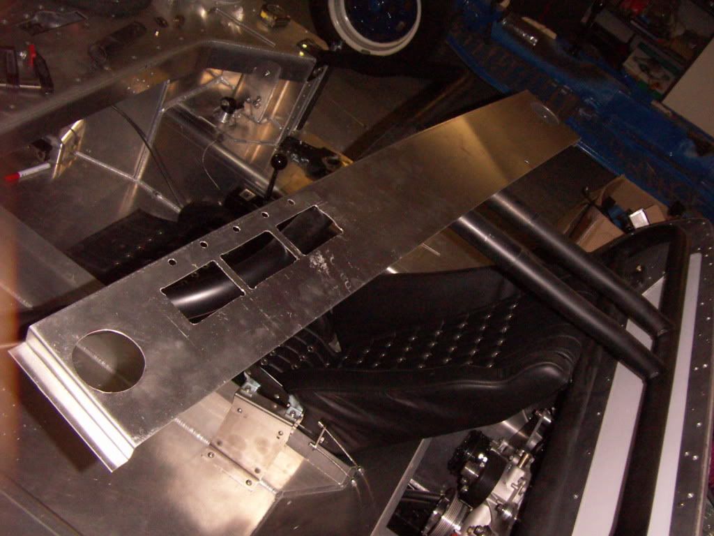
AC and heat air plenum:
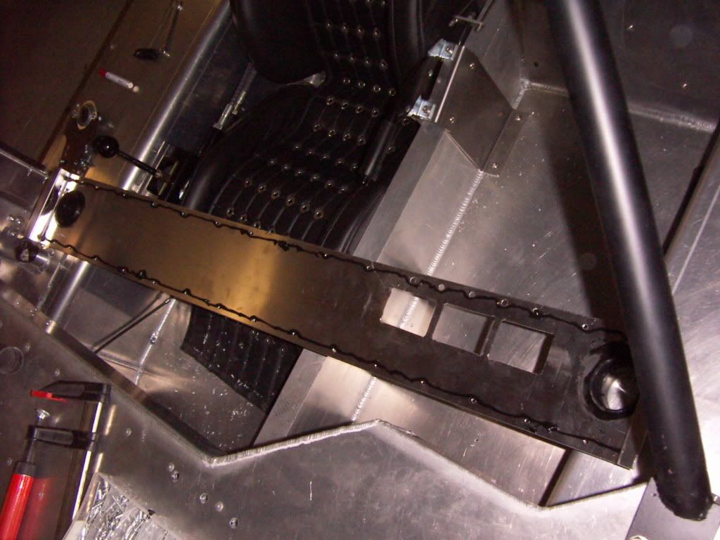
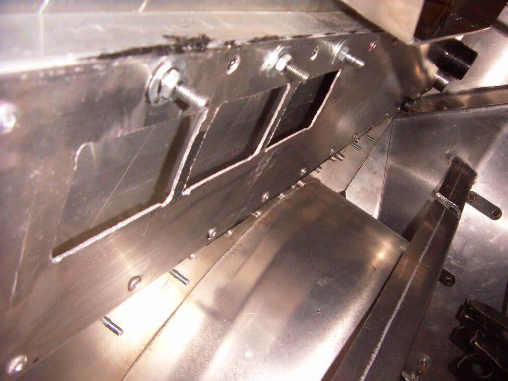
as i want to be able to take out the dashboard without removing the rollcage, i needed a different solution for the plenum. I also didn´t want to partialy or fully take out the 1" square tube reeinforcing bars underneath the dash area.
the solution is a aluminium sheet to cover the two reeinforcing bars and thus creating a plenum by doing so. I used 1,5mm aluminium sheet on which i folded the ends to close the "tunnel". Holes for the Evaporator outlets where cut in as well as holes for the hoseadaptors going to the eyeball vents.
It was than glued on with PU glue and riveted on the bars.
I still need to remount the dashboard to cut the hole which feeds the windscreen demister.
aluminium cover with holes for evaporator and hose adaptors
Hose adaptor mounted
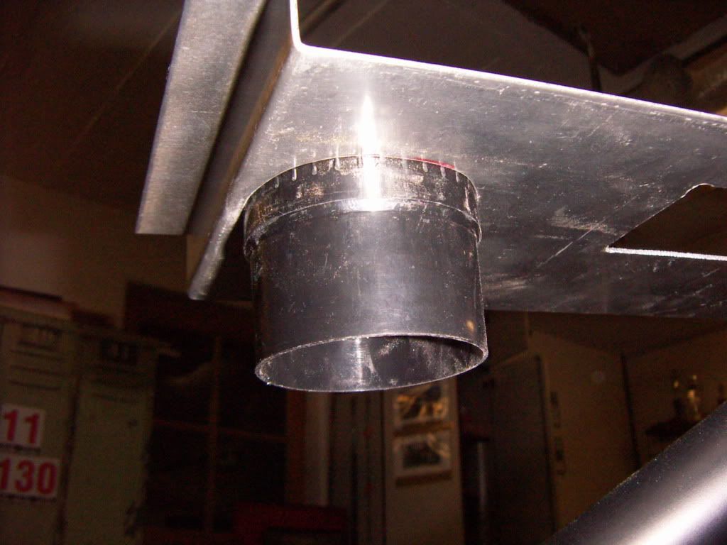
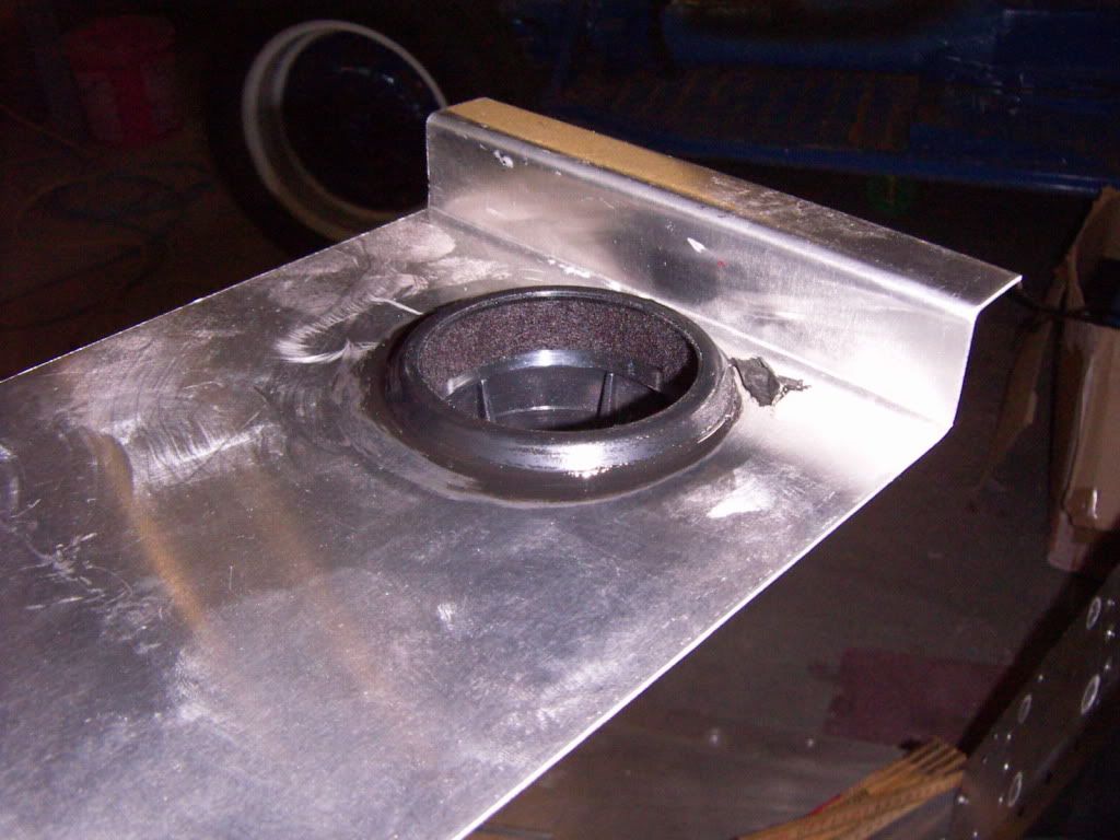
Sealing with PU, ready to be riveted in
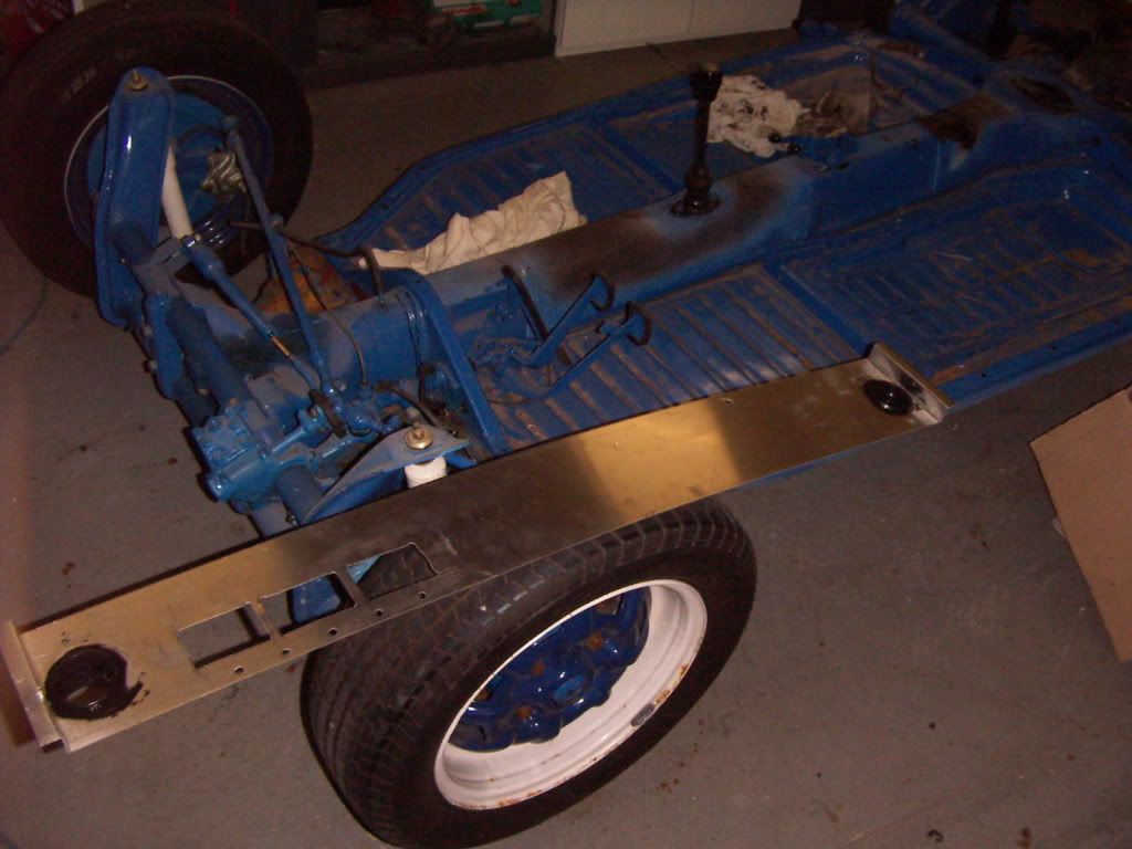
The finished plenum
TOM
AWH: 622h
as i want to be able to take out the dashboard without removing the rollcage, i needed a different solution for the plenum. I also didn´t want to partialy or fully take out the 1" square tube reeinforcing bars underneath the dash area.
the solution is a aluminium sheet to cover the two reeinforcing bars and thus creating a plenum by doing so. I used 1,5mm aluminium sheet on which i folded the ends to close the "tunnel". Holes for the Evaporator outlets where cut in as well as holes for the hoseadaptors going to the eyeball vents.
It was than glued on with PU glue and riveted on the bars.
I still need to remount the dashboard to cut the hole which feeds the windscreen demister.
aluminium cover with holes for evaporator and hose adaptors
Hose adaptor mounted
Sealing with PU, ready to be riveted in
The finished plenum
TOM
AWH: 622h
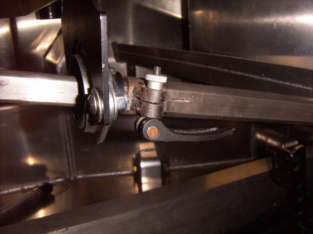
Adjustable steering column:
I adapted the steering column to fit my needs . I took out one of the universal joints and replaced it with a outer D tube.
I also wanted to be the steering column colapsable and adjustable.
I welded on a thickwalled tube on the outer D tube and cut in notch with the hacksaw. The D tube is compessed via the means of a mountainbike seat fastener which is a excentric bored lever and thus providing enough force to fix the inner column but in a case of crash "hopefully" will alow the inner tube to slide within the outer one.
It works great ( just the crash case is diffcult to simulate, may be i will go on the hydraulic press and check how many force it needs to collapse ít) and it is a nice feature in combination with the adjustable pedals to be able to adjust the car to every driver now.
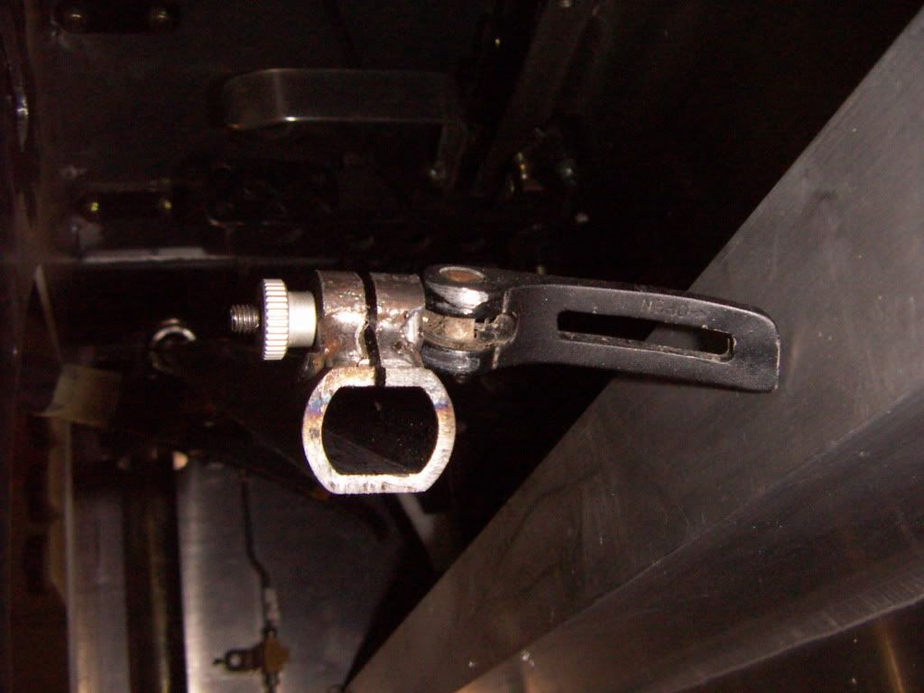
I will look to find one of these with a 6mm bolt instead of the now 4mm
TOM
AWH: 624h
I adapted the steering column to fit my needs . I took out one of the universal joints and replaced it with a outer D tube.
I also wanted to be the steering column colapsable and adjustable.
I welded on a thickwalled tube on the outer D tube and cut in notch with the hacksaw. The D tube is compessed via the means of a mountainbike seat fastener which is a excentric bored lever and thus providing enough force to fix the inner column but in a case of crash "hopefully" will alow the inner tube to slide within the outer one.
It works great ( just the crash case is diffcult to simulate, may be i will go on the hydraulic press and check how many force it needs to collapse ít) and it is a nice feature in combination with the adjustable pedals to be able to adjust the car to every driver now.
I will look to find one of these with a 6mm bolt instead of the now 4mm
TOM
AWH: 624h
Tom:
Very nice solution to the air plenum issue.
The adjustable steering column is a nice feature. Fran did something similar for us, although Ryan and I have always left it in the same position despite the fact I am vertically challenged compared to Ryan. The pedals, however, do get adjusted for different drivers.
Your attention to detail is amazing.
flatchat(Chris)
Supporter
Tom , you have astounded us with many great ideas on your build project --today should be the ultimate in inspirations
Happy Birthday! - mate. :thumbsup:
Happy Birthday! - mate. :thumbsup:
Thanks guys,
Chuck you know me very well. I went home 3 h earlier than usual for the official family coffee table, but soon enough i sneeked into the workshop and worked 1h on the car. Now i´m back to family duties, because we have a very important other birthday today. My Son Michael turns 18 today ( yes our birthday is on the same day, a good planning in everything is half the win), which is basically the same as turning 21 in the US.
Got to go we are heading out for a nice steak dinner now.
TOM
Tom,
Congratulations on another one. Have a fun birthday, cause the older we get the fewer there are to have. I hope you are passing on the skills to your son!!
Bill
Congratulations on another one. Have a fun birthday, cause the older we get the fewer there are to have. I hope you are passing on the skills to your son!!
Bill
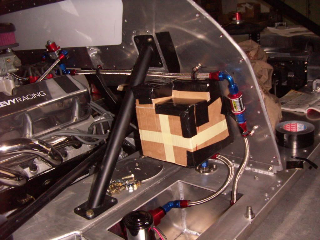
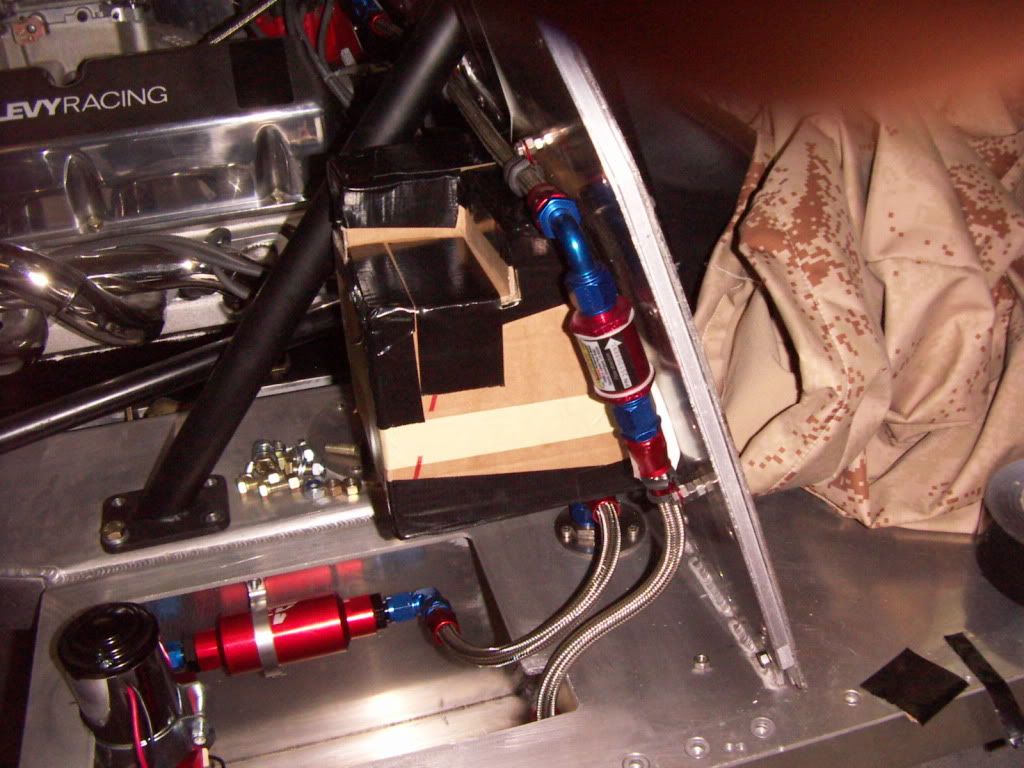
Did a mock up for my expansion tank.
I wanted it to look similar to an original one. Volume is about 4,5 liter (1.2 gls).
There will be three inlets.
one from the 5/8" from the waterpump ( running into the bottom)
one AN 3 from the rear of the intake ( running into the top)
and one AN3 from the bleeder opening of the cooler ( running into the top)
With that volume it should be plenty reserve for expansion ( the volume increases about 5% from 20°C to 100°C)
Thinking about that i would even make it smaller (2,5 l).
It will be fabricated from 2,5 mm Aluminium ( AL MG3)
What you think ?
TOM
- Status
- Not open for further replies.
Similar threads
- Replies
- 46
- Views
- 9K