Tornado TS40 Build Belfast Northern Ireland

Hi Keith,

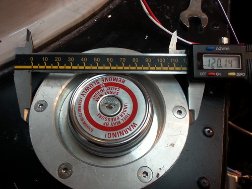
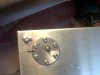
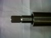
Regarding the filler caps, according to the regs they don’t have to be lockable, but they do have to be tethered. I used brake cable from a push bike and made the crimps out of a small length of brake pipe

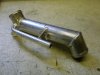
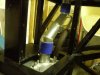
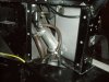
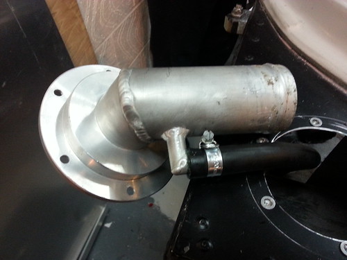
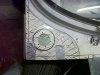
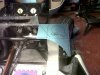
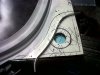
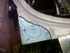
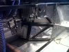
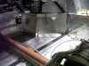
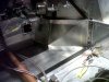
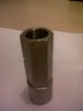
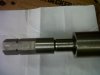
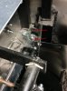
The filler flanges and tank will need to be modified to add a separate vent line, otherwise the tanks won’t fill properly see attached. Note the blue silicon hose was for mock-only as it’s not fuel resistant. The smaller line is the breather line to atmosphere which gores through the roller-over valve (stops fuel spilling if the car is inverted)

Regards,
Andy
 

Attachments

  • P6191345.jpg
    P6191345.jpg
    161.6 KB · Views: 410
  • P7181508.jpg
    P7181508.jpg
    167.7 KB · Views: 421
  • P5192134.jpg
    P5192134.jpg
    182.7 KB · Views: 410
Andy,
On your last pic is the second small hose a vent line from the other end of the tank?? You will need one for when you are parked on a down grade. The expanding bubble at the back(heat)will force fuel up the filler pipe and then burp out the vent line in spite of the roll over valve. They are pressure limited(at least i think mine is), and you will get fuel into the interior.No?? Is yours different??

Bill
 
Hi Bill,
yes there are 2 tank vents, one at the front and a second at the rear to prevent the situation rising that you've described

Regards,
Andy
 
Keith, you can just download the latest. From v9

A fuel filler cap must positively locate to the filler neck and incorporate an adequate sealing arrangement so that a fuel leak is not possible.
  1. The fuel filler cap must either be tethered to the vehicle or be of a lockable type where the key can only be removed when the cap is locked or an automatically opening and closing, non-removable fuel filler cap
(Post 0 5 / 2009 vehicles only)​
 
Guys thanks, I do have the later IVA doc,... I got confused, too many PDFs; anyway it looks like tethering is the easiest option, still. Andy thanks for the pix, I have some stainless braid from a work prototype, all I need now is sharp pliers.
 
Cheers Brett, can I ask do you have a breather from the rear of the tanks as well, or just the front? Both Bill and Andy have a rear breather, which I don't have at present. So that seems like another small mod. My tanks are foam filled and at least on has had fuel in, I am thinking about a screw-on connection for the rear breather, as opposed to welding. Possibly I can push the foam out of the way via the level gauge access hole and either fit an attachment or get a stub pipe welded on? K
 
Yes, I will be installing a rear breather on both tanks. I have -6 bosses welded in and will be attaching to a Think roll-over valve.

How is your tank set up? If you have a float vale for your fuel level, you must have a void space to allow the float to work and therefore could weld a boss in. If it is a dip valave you can push the foam back and then release when it cools down.

If you have fuel in one, then I would be very careful before you weld!

BTW I may have a spare rollover valve somehwere, as I managaed to buy an extra one along the way somewhere
 
Brett, not sure about the gauge, I believe the std Tornado is a float on a lever, I'll PM or email you re. the valve,.... in the unlikely event,..... K
 
This weekend I was working on the panels for the filler caps and the front apron, managed to get the panels on and the front apron cut. Unfort the previous owner had cut the holes in the apron but because I had repositioned all the body panels, these holes were in the wrong place. I thought is best to panel this area and put the fillers through a panel rather then the fibreglass apron.

I'm thinking of using riv-nuts for the roof section, so it can be removed easily, so I riveted where needed and left the riv-nuts for later as I'll need to drill through the apron, ally and chassis in one go.

I used a bent (carefully formed) piece of ally to define the curve for the cut.

Later this week hope to get the front of the roof section repositioned on the car and the riv-nuts inserted, then I can move on to the tanks, breathers and vents.
 

Attachments

  • IMG01459-20140126-1752.jpg
    IMG01459-20140126-1752.jpg
    191.8 KB · Views: 344
  • IMG01470-20140201-1614.jpg
    IMG01470-20140201-1614.jpg
    211.4 KB · Views: 318
  • IMG01473-20140202-1644.jpg
    IMG01473-20140202-1644.jpg
    162.1 KB · Views: 325
  • IMG01476-20140202-1646.jpg
    IMG01476-20140202-1646.jpg
    161.1 KB · Views: 353
  • IMG01487-20140202-1740.jpg
    IMG01487-20140202-1740.jpg
    162.4 KB · Views: 335
Fitted tank breathers (Mocal) to the rear of both tanks, as the clearance height it low I used some that had a connector at 90 degrees. The front breathers are an inline type and will be attached to the inside of the panelling around the main filler pipes.
 

Attachments

  • IMG01502-20140208-1346.jpg
    IMG01502-20140208-1346.jpg
    169.6 KB · Views: 335
Also panelled the footwells, awkward to do with all the other panels done, the EPAS had to come out, the pedals had to be moved,....the shapes and bends are a pain too, at least it will be covered with carpet, I hope. put in some lead sound proofing to deaden the road noise, would I ever have heard it?
 

Attachments

  • IMG01504-20140216-1321.jpg
    IMG01504-20140216-1321.jpg
    167.5 KB · Views: 389
  • IMG01506-20140216-1858.jpg
    IMG01506-20140216-1858.jpg
    179.1 KB · Views: 324
  • IMG01507-20140216-1915.jpg
    IMG01507-20140216-1915.jpg
    177.9 KB · Views: 346
Electrical circuits

Can I ask my viewers how many fused circuits do you have and how many relays, I want to get the fuse and relay boxes ordered.

Relays, I'm thinking, fans (1), water pump (2), EPAS (3), winkies (4), headlights (5), starter (6), maybe,.... I have no A/C.
 
From Memory

Relays (original) 7 in total

Starter
Dips
Mains
Indicators
Fans
Fuel Pump x 2

Relays (added)
3 x Fused protection (I diverted the power from going through the iginition switch)
Timer Relay with normal for Intermittent Wipe
Changeover relay as I am only going to be running 1 Fuel Gauge
Lower Spots/Driving Lights
Rear Fog Relay for new IVA requirements

In total I will be having 24 fused circuits. 16 came with the loom that I got, but I have added in another box for additonal circuits that I have added (separated out the Rear Fog, Spots, Water Pump, Door Locks, Mirrors and some others I can't remember as I write this). The below shows how I have mounted the boxes along with the EWP Controller and in the background you can see the original fuses


Untitled by Brett-GT40, on Flickr
 
Got my new steering wheel adapter back from the workshop. The top of the Corsa C EPAS is a 21.5mm splined shaft that did not fit into the previous hex adapter which had a 19mm hole,... I could have made it fit but we would have to have removed too much material making the wall too thin. I just need to weld it on now.
 

Attachments

  • IMG01513-20140224-1830.jpg
    IMG01513-20140224-1830.jpg
    125.4 KB · Views: 338
  • IMG01510-20140224-1825.jpg
    IMG01510-20140224-1825.jpg
    61.5 KB · Views: 297
  • IMG01514-20140224-1831.jpg
    IMG01514-20140224-1831.jpg
    128.4 KB · Views: 309
The throttle pedal was a bit stiff and did not have a lot of travel, so moved the cable connection point closer to the fulcrum, hopefully killing 2 birds. The travel before the move was about 4cm, now I have about 6cm and it is much freer. FYI, I moved the connection point in by about 2.5cm (1").
 

Attachments

  • lever.jpg
    lever.jpg
    78.7 KB · Views: 315
Back
Top