Tornado TS40 Build Belfast Northern Ireland

Spent the August bank holiday Monday getting the Corsa EPAS in place. Tacked the front bracket in position and bolted the Corsa EPAS column to it, it's a bit awkward getting the correct angle (~14 deg) and height as well as centring it with the dash. With the front bracket in place and the column secured to it, I'll now make the other brackets to fit a bit ad hoc, rather than designing them.
 

Attachments

  • IMG01303-20130826-1930.jpg
    IMG01303-20130826-1930.jpg
    126.3 KB · Views: 460
  • IMG01307-20130826-1948.jpg
    IMG01307-20130826-1948.jpg
    222.3 KB · Views: 440
  • IMG01309-20130826-1952.jpg
    IMG01309-20130826-1952.jpg
    191.8 KB · Views: 471
  • IMG01311-20130826-2027.jpg
    IMG01311-20130826-2027.jpg
    195 KB · Views: 443
  • IMG01310-20130826-1958.jpg
    IMG01310-20130826-1958.jpg
    194.7 KB · Views: 479
Did some more EPAS bracket work a few days ago, I summarise here in glorious technicolour. One cardboard bracket to go, final pic.
 

Attachments

  • IMG01327-20130904-1727.jpg
    IMG01327-20130904-1727.jpg
    188.6 KB · Views: 357
  • IMG01332-20130904-1853.jpg
    IMG01332-20130904-1853.jpg
    178.9 KB · Views: 373
  • IMG01338-20130908-1634.jpg
    IMG01338-20130908-1634.jpg
    210.2 KB · Views: 386
  • IMG01330-20130904-1803.jpg
    IMG01330-20130904-1803.jpg
    193.5 KB · Views: 370
  • IMG01342-20130908-1821.jpg
    IMG01342-20130908-1821.jpg
    219.6 KB · Views: 365
Water pump bearing assembly was next on last night's hit list, grind-weld-grind.
 

Attachments

  • IMG01270-20130818-1610.jpg
    IMG01270-20130818-1610.jpg
    234.5 KB · Views: 354
  • IMG01344-20130909-2000.jpg
    IMG01344-20130909-2000.jpg
    195.2 KB · Views: 361
  • IMG01346-20130909-2005.jpg
    IMG01346-20130909-2005.jpg
    220.9 KB · Views: 357
  • IMG01349-20130909-2125.jpg
    IMG01349-20130909-2125.jpg
    209.6 KB · Views: 375
  • IMG01353-20130909-2149.jpg
    IMG01353-20130909-2149.jpg
    253.6 KB · Views: 378
Hope you checked for foot clearance before you finish it all off. I have to be careful which shoes I wear for mine to clear. Another project for this winter.

Bill
 
Hi guys, I'm heading in the right direction, I can just about hear the vroom, vroom in the distant future. Bill, i did indeed check the clearance, a spare pair of shoes, actually still in there, probably trapped.

On the EPAS timer we have a final circuit under test, the final version does the following:-
Immediately after engine start, the timer waits 10 secs before outputting the speed and rev pulses to the EPAS.
It then gives 30 secs of high assistance (low speed) to allow you to unpark.
It then reverts to low assistance (high speed).

A button push will give you 60 secs of high assistance, to park, after which time it will revert to high speed (low assistance).
A long 5 second push and hold on the butttton will turn the timer off and stop all pulses to the EPAS ECU.

All this is easily changed, I'll email you some further info. k
 
Wanted a few days of easy work, have been doing stuff like positioning the reversing and rear fog lights. The Gulf vents are simply taped in place to aid me to position the lights. Done some other minor things, will post pix when i get round to taking them,... see how lazy I've become lately. K
 

Attachments

  • IMG01366-20130922-1549.jpg
    IMG01366-20130922-1549.jpg
    160.2 KB · Views: 430

Renato

Lifetime Supporter
Hi Keith,

Looking good! Your progress is great.
I find that flipping between different tasks makes it more interesting and keeps the pace going!

Regards,
Renato
 
Hi Renato, thanks for the feedback, there is sooooo many things to do that some days I plan nothing and just go to the garage and do whatever takes my fancy! K
 
Oh Brett, too late, holes cut, lamps set in, I just need to glass the rear. I did toy with the idea of placing them behind the grilles, but decided to put them where shown. It only took a morning,.... when cutting into the body I always dither! K
 
Been taking it easy on the car lately, "....you spend more time in that garage with that car............" you guys know how it is.

Anyway had some bits in the workshop getting welded. Got the heater feed on the thermostat plugged and a bead welded around the hose connector (top right). Made a feed and return for the heater water from the main water circuit, hope I get enough pressure from them (bottom)? Also got 2 new connectors for the water feed into the block (top left).
 

Attachments

  • Ally Weld.jpg
    Ally Weld.jpg
    167.7 KB · Views: 354
Got my Corsa C EPAS 'assistance controller' finished, I did not want to fit a knob on or near the dash!

My circuit has a 10 second delay upon start-up before it outputs any pulses, then it outputs a constant rev signal for the ECU to know the engine is running. it also outputs a low speed (high assistance) for a period of 1 minute, to allow you to 'unpark'. It then automatically reverts to the high speed (low assistance) until the button is pressed, which will give you 1 minute of high assistance, and automatically reverts to low assistance after the minute.

If you press and hold the button for 5 seconds it turns the circuit off, likewise if you press and hold for 5 seconds it comes back on again.

I managed to source the connector plug used on the Corsa C EPAS ECU. Let me know if you like what you see, battery is just there you give you a feel for the size, I have an ABS enclosure for it also.
 

Attachments

  • EPAS09.jpg
    EPAS09.jpg
    115.1 KB · Views: 317
  • EPAS-CONN.jpg
    EPAS-CONN.jpg
    107 KB · Views: 315
Finally got the Corsa column in the car. When I bought the column it came with a telescopic adjustable lower link shaft which mates with the corsa rack. I was able to take this link shaft apart and keep the upper universal joint that mates with the column, I then took the original link shaft which mates with the GT40 rack and got it turned down on a lathe, so it slides inside the corsa shaft, then welded them together.
 

Attachments

  • IMG01324-20130831-2022.jpg
    IMG01324-20130831-2022.jpg
    253.9 KB · Views: 324
  • IMG01438-20131221-1846.jpg
    IMG01438-20131221-1846.jpg
    190.4 KB · Views: 304
  • IMG01440-20131221-1847.jpg
    IMG01440-20131221-1847.jpg
    192.9 KB · Views: 316
  • IMG01432-20131208-1532.jpg
    IMG01432-20131208-1532.jpg
    115.1 KB · Views: 328
Got the water system re-plumbed during the Christmas break. I had originally removed the mechanical pump from the engine block for 2 reasons, first to save me having to run the heater hoses down the centre tunnel and second to remove the hump on the rear bulkhead. Of course like many/most 'remedial' jobs that at first glance to be straightforward, it turns out to be of epic proportions. I originally planned to reuse the old mechanical pump as a manifold by simply removing the impellor.....

BUT I was not satisfied with the design of the original pump, the back plate is flimsy and therefore prone to leaks, so decided to remove the old pump completely. I then had to source and/or make new connections onto the block as well as source a thermostat to be located the front bay with the new electric water pump. None of the original pipes has been swaged, I therefore had to get that done to all the existing metal pipes. Some were done manually by pressing nipples around the circumference with a tool, for aluminium pipes and connections I got a bead welded around the edge.

Alternator mounting had to be changed, new fan belt sourced, feed and return coupling had to be made for the heater hoses,....

After debating in my mind various designs I decided to invest (heavily) in silicone hoses. Many of the pipes to be used were of differing diameters (block connections are 25mm, old t/stat is 38mm, the copper pipes down the centre are 35mm, the radiator is 34mm the new t/stat 32mm new water pump 38mm.......

Anyway I post here the mark I solution, it's not a pretty as I'd like, the angles were not working with me,.... let's see if it works?

K
 

Attachments

  • rear-water1.jpg
    rear-water1.jpg
    195 KB · Views: 386
  • rear-water2.jpg
    rear-water2.jpg
    108 KB · Views: 336
  • front-water.jpg
    front-water.jpg
    205 KB · Views: 382
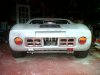
I have moved to some bodywork and the elusive quarter inch. Looks like the central spider had been wrongly positioned by the pervious owner; on the Tornados the back of the roof legs should be 14" from the chassis member of the rear wheel arch, one side was 13.5" I could just about take out the error with huffing and puffing. The other (driver's) side was 13", so needed to be re-drilled, there was also a lot of huffing and puffing, mostly disguised as bad language. I found some carpet offcuts that are exactly 1/4" thick so have been using them to maintain the gaps around the edges,.... errr I think I am getting there.

When the roof was corrected the rear clip did not engage in the rain channel, so it is now unbolted and repositioned in the correct place and is now sitting in position on bricks and wood, ready for the drill.

As the doors had been fitted wrt the mal positioned roof, the driver's door is now out by an inch, so the hinges need moved forward, anyway I'm leaving that for later.

The front clip is out of whack too. Anyway, Monday evening will see the rear clip drilled and bolted in the correct position. hopefully I'll get the front apron of the roof section provisionally positioned, then the front clip can be corrected later this week, oh and the doors.

does anyone know of a log detailing body fitting, things like setting the gaps, affixing the sills etc,..
 
Hi Keith,
I wouldn’t worry too much about the plumbing of the coolant pipes onto the engine. Once the bulkhead access panel is fitted, you can’t see a thing!

Regarding fitting the sill covers, I’ve used M6 Socket Head Flange Button Screws.
Regards,
Andy
 

Attachments

  • M6 ScrewBolt.jpg
    M6 ScrewBolt.jpg
    12.6 KB · Views: 258
Back
Top