ZF Half Shaft Bad Vibes

Chuck

Supporter
Bad vibes
<?xml:namespace prefix = o ns = "urn:schemas-microsoft-com
P><o:p><P style=
I think there is an issue with the half shaft, but don’t have enough experience to know. Today was our first drive since rebuilding the engine and drivetrain. First drive with the half shafts.
<o:p></o:p>
Driving down our street there is significant vibration. More speed, more vibration. It is related to road speed, not engine speed. The gear one is in makes no difference. It continues when the car is in neutral, rolling down the street. We never got over 30 MPH or so. It is noticeable even when barely moving. It feels like an engine that is lugging – that same sort of jerking sensation.
<o:p></o:p>
We jacked up the rear wheels and removed the half shafts. Running the engine through the gears it ran smooth. No bad vibes.
<o:p></o:p>
While jacked up we also ran it with the half shafts in place but without the wheels. The vibes were there but not as bad.
<o:p></o:p>
Then put the wheels on and ran it jacked up in the garage. Putting it in top gear really made it vibrate!
<o:p></o:p>
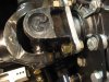
The U joints were carefully checked to make sure nothing was binding. A couple of spots of paint had eroded off, so we removed the half shafts and ground a bit more until we were comfortable there were no issues with binding. Note the piece of paper in the picture. I could be wiggled easily confirming the clearance. Now I should point out that it is tight clearance: probably around a sixteenth to an eighth of an inch. But even after grinding away more metal it persisted.
<o:p></o:p>
After grinding away we repainted the exposed metal. Drove it again. No erosion of the fresh paint whatsoever, so it would seem the clearance within the U joints is not an issue.
<o:p></o:p>
A clutch problem crossed our minds, but I don’t think so. When driving, say 25 MPH, you can push the clutch in and feel a jerking through the drive train, then slide it into neutral and it goes away. The drive train seems smooth when in neutral, but the road speed related vibration persists. It is almost like a jerking sensation. When stopped one can put it in neutral, release the clutch, and rev the engine or put in gear with the clutch pushed in and rev the engine: smooth as glass. I think it is something with the half shafts transmitting the jerking forces forward through the tranny.
<o:p></o:p>
The half shafts are not balanced. Surely that is not an issue?
<o:p></o:p>
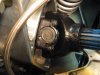
The yoke is fastened to the stub axle with half round straps, per the picture. It does not seem like the best arrangement. Should there be a shim or something between the strap and the yoke end?
<o:p></o:p>
I don’t think the rear wheel bearings are in issue. The wheels are absolutely snug and don’t give any indication of a bearing problem.
<o:p></o:p>
With the rear wheels off the ground and being turned by hand, the half shafts operate smoothly without a hint of problem
<o:p></o:p>
The engine is running just fine. Starts well. Revs well. Sounds great.
<o:p></o:p>
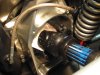
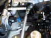
Surely the angle of the half shaft should not be an issue. It angles downward and rear ward slightly. That would be virtually impossible to change based upon the tranny location.
<o:p></o:p>
I am puzzled.
</o:p>
 

Attachments

  • HalfShaftStubAxle.JPG
    HalfShaftStubAxle.JPG
    154.7 KB · Views: 426
  • HalfShaft6.JPG
    HalfShaft6.JPG
    191.6 KB · Views: 390
  • HalfShaft7.JPG
    HalfShaft7.JPG
    161.4 KB · Views: 430
  • HalfShaft5.JPG
    HalfShaft5.JPG
    178 KB · Views: 428

Chuck

Supporter
Funny how putting pen to paper, or fingers to keyboard, makes you think of things.

Another question, which I fear will reveal my ignorance of such matters.

Should the U joints at the ends of a shaft be 90 degrees out of phase? 180 degrees?

On one half shaft they are in the same position (shown in the picture). On the other they are about 30 degrees out of phase. Something tells me they should be 90 degrees.

Somebody educate me!
 
HI Yes you answered your own question. These should be in line, Not rotated This is called Phasing and even a twist in one can give Vibration. ( ask Me how I know )
 
One in your rh pic is correct I think, dwg attached to be sure... hopefully a simple matter of removing one end and rotating one or two splines unless the guy who built it left his B.O.G..:)
 
Last edited:

Chuck

Supporter
Thanks guys. After my last post went out and aligned the one that was a bit out of phase. Fired it up while it is still sitting on jacks. No more bad vibes! Did it just as you have illustrated Jac.

Forcast is for a winter storm starting tommarow . . . so the first really good drive will be put off again . . . .

And did this whole little project during the Super Bowel. . . . one must have priorities. . . .

Thanks for the quick response and dead on correct answer
 

Julian

Lifetime Supporter
Correct the joints should be 'out of phase' at 90 degrees to cancel each other out, so as one joint speeds up the other is slowing down.

Vibrations will be worse at acute shaft angles due to the elliptical motion of the joint and yours appear to be running at quite an angle, IMHO from the photo (assuming the car is on the ground and not jacked up) probably more than recommended for half shafts.

A U-joint can theoretically run at 30 degrees but there is a practical limit based on rotation speed and I think it's somewhere around 10 degrees. This is one reason why most people end up going with CV axles, which can run at much acuter angles.
 
Chuck, remember to keep those splines coated with a good grade of high-tack (resistance to flying off) or marine grease,at least a bit farther than the anticipated working range. A.J.
 
Phasing as in picture four is correct.

Also check that you have clearance on your axles under full plunge, I have seen a car run smooth at droop then awful vibration when driving. He did not allow enough end clearance for plunge, an allowance for extra plunge due to bushing compliance should be added as well.
 

Chuck

Supporter
Good tips. Thanks.

Now I am a bit confused: 90 degrees out of phase or both ends on same plane (0 degrees)? Putting them on the same plane, as illustrated by Jacmac, got rid of the vibration. But would 90 degrees out of phase be better?

Pictures may be deceiving. I doubt the angle is any where close to 30 degrees, but probably a bit more than 10. Given the parameters of a ZF, engine height above ground level, and ride height dictated by the GT40 design, it would seem that the angle would be pretty consistent from one car to another.

Yes, we made sure the U joints did not bind at the limits of travel. Took a fair bit of gentle griding on the stub axles and U joint ends.

Good tip on the grease. My expectation is that checking the bolts that secure the U joints and greasing will be part of the routine 'pre flight' check list. A failure in that area at speed would not be a pretty sight.
 

Dave Bilyk

Dave Bilyk
Supporter
Chuck,
90degs for the following reason, if I can explain succinctly;

Consider a single joint (i.e just one end of the half shaft);
When the input and output are in line, output speed = input speed all is smooth rotation.

articulate the joint (a few degrees bump or droop) and the mechanics of the joint mean that the output (half shaft) is no longer rotating smoothly, it speeds up and slows down a little (twice per rev) as the joint rotates.

Now consider the other end of the half shaft;
(the transaxle output stub and the wheel hub drive are parallel, and the drive shaft is angled between them)
If the joint is in phase (0deg) with the other, it will do the same thing, and there will be twice as much oscillation at twice per rev.
In this case you will excite torsional resonance at certain speeds. (especially when on the road since the tyres are part of the drive train torsional system.

However, if the joint is out of phase (90deg), this means that the torsional oscillation at 2x per rev will be 180deg (2 x 90deg) out of phase, i.e it will cancel out the oscillation of the first joint.
So visualise a constant rotation speed at the transaxle output, producing a 2x per rev speeding up and down of the half shaft, and a constant output speed. weird but true.

If the halfshaft is level with no bump or droop, everything will be smooth, but if the joints are in phase, a constant speed output from the transaxle will try to speed up and slow down the wheels 2x per rev, exciting any torsional resonance in the drive train at the appropriate speed.

I was going to draw a picture but don't have time here at work, happy to do it later if the above is not well put.

Dave
 
Dave, I reckon your theory would be a good one for myth busters. I fail to see how a shaft after a uni joint can be speeding up and slowing down when it is being pushed by a constant speed. Fair enough the joint wobbles back and forth (for the want of a better term) as it compensates for angular misalignment but at the centreline of each shaft the speed would be constant??
Kind regards, Gus.
 

Chuck

Supporter
Dave:

Your explanation makes sense, and indeed a 90 degree alingment was my first instinct once I gave it a bit of thought. But as I reflect further, I am not so sure.

Now I am no engineer. I do undersand that the half shaft will change speed as it rotates, depending upon the angle. So far so good.

But lets assume that the tranny output shaft and the stub axle are always parrallel. Lets also assume that the yokes on the ends of the half shaft are aligned, not 90 degrees. If that is true, than the accelleration and decelaration of the shaft would be cancelled out at the stub axle end since the yoke at that end woudl be going through the same longer arc at the same point as at the tranny end. Thus the stub axle would be rotating at the same constant speed as the tranny output.

I noticed that the drive shaft on my Cobra had the yokes aligned seeminly supporting this notion.

I am no engineer, but this seems to make logical sense. Guess I need to drive it with the yokes aligned and see just how smooth or not is really is . . . . once the snow storm passes . . . .

Might be an interesting experiment to also put it 90 degrees out of phase and give that a try as well.

Ryan suggested looking at some original GTs to see how they did it. I told him that would be a cop out. Too easy.
 

Chuck

Supporter
Terry:

Nice graph. That would seem to suggest that the problems with the half shafts go up exponentially and that one should keep it below 30 degrees. And below 15 degrees would be really good.
 
Theory is all fine and well, but in reality, halfshafts are always oriented with the inner yokes in the same plane and the outer yokes in the same plane as one another, as Jac Mac so deftly illustrated above. I don't know for a fact that clocking them 90 degrees out would be problematic, but I'm willing to bet that it would be. Furthermore, I'd be willing to bet that due to the way they are made, it wouldn't even be possible, as the spline count is probably configured in a manner that only allows a single, proper orientation.

Given that they are balanced, it's critical that the pieces are kept together and not mixed-and-matched. Most such driveshafts have alignment marks of some kind on them as well. Pantera driveshafts have tiny arrows stamped into each half, which point directly to one another when they are assembled correctly.

Even a slight misalignment can prove disastrous. Many years ago, a planned journey across Europe in a Mangusta was wrecked when my friend picked the car up from a shop that had done a ton of work to it just a day before our departure, and it shook like a wet dog! It was absolutely undriveable above about 40 mph.

The driveshafts are very visible on a Mangusta and I was able to spot the problem right away. Unfortunately it wasn't a simple problem of disassembling them and re-clocking them; one of them had been 'repaired' and the yoke had been welded on at the wrong angle, making it a hopeless case. We had to take his Bristol 411 on the trip instead.

As an aside, when he returned home, he arranged to have CV-joint driveshafts made by the outfit that manufactures all the driveshafts for the F1 teams, and that turned into a three-ring circus as well. He shipped them one of his driveshafts for reference for the bolt pattern, length etc., waited an eternity and then discovered they'd bloody lost it! He then guardedly sent him the other one, they took ages to produce (another six months or something crazy like that?), and finally they sheepishly sent him a delectable set of CV joint driveshafts and just gave them to him for free! :laugh:
 
You gentlemen are engaged in an interesting discussion regarding u-joints - my situation is somewhat different. I have cv-joints on the transaxle side and u-joints on the wheel hub side. I pick up vibration and some have argued that this is the problem with my vibration. Anybody care to comment on this arrangement!

John
:coolgleam:
 
http://www.hurst-drivelines.com/files/Universal_Joint_Alignment_Proc_111606.pdf

U-joints do not turn at an even speed. The greater the angle, the greater the
speed or velocity changes as the driveshaft turns. In other words, as the ujoint
travels around to the outside of its angle it slows down. When traveling through
the inside of the angle it speeds up. The greater the operating angle is, the
greater the speed difference is. Having the opposite ujoint at the same, but
opposite, operating angle cancels out this speed difference and keeps harmonics to a minimum.
 
You gentlemen are engaged in an interesting discussion regarding u-joints - my situation is somewhat different. I have cv-joints on the transaxle side and u-joints on the wheel hub side. I pick up vibration and some have argued that this is the problem with my vibration. Anybody care to comment on this arrangement!

John
:coolgleam:

you should use one type or the other. do not mix. the c/v joint make the drive shaft travel at a constant speed and the u joint makes it travel at a non constant speed , so you are constantly twisting and un twisting the drive shaft. not good
 

Dave Bilyk

Dave Bilyk
Supporter
Chuck, Mike,
on looking again at my comments, my logic had missed the point that with parallel input and output, the joint angle is down (-ve) at one end and up (+ve) at the other, which makes them self cancelling when in phase (yokes in line). So I think I have it right now and agree.

John, +1 on Lynns comments.

Gus, you're right it would be a good one for mythbusters, but not as exciting as shooting, wrecking or blowing stuff up:) as I said weird but true.

I'm almost tempted to build a test rig to demonstrate this to myself, I think a few bits of 1/16" to 1/8" welding wire could be used to make a simple demonstration. Anyone with time on their hands?:)

Edit. by the way, no-one said that CV stands for Constant Velocity.

Dave
 
Further to the chart posted by Terry;

Numbers from my 'old' Mechanics of the motor vehicle text book, dwg to hopefully make it simpler to understand.

Wanni mentioned in one of his tech explanations that F1 car halfshafts twist a number of revolutions at the start of a GP ( not just a few ° but actual multiples of 360°), with that in mind there is no way the humble U-Joint could survive in that enviroment as it destroys itself when forced to run out of phase, which in turn means the driveshaft also must be very robust in construction.
 
Last edited:
Back
Top