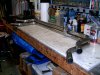
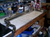
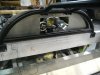
Decided to remake the upper firewall. In the process added an access 'window' because you just know - someday - it will save my ***. Also located and tapped all the flange mating holes. Sat the body back on the chassis (how many times now?) and bolted it all together, it's really strong, makes the rear upper spider rock solid. Since Fran says RCR now offers this flange (you won't need to make it like I did) I highly recommend ordering up.
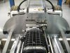
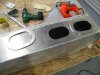
Then there is that cool surge tank, thanks Howard. Now getting started with the fuel system, here are some bolt flanges to be tacked under the lid.
Then there is that cool surge tank, thanks Howard. Now getting started with the fuel system, here are some bolt flanges to be tacked under the lid.
")
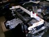
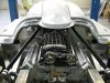
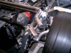
") Those items are the coolant tubes in my car and no, that is not the correct location for them :huh2:
Those items are the coolant tubes in my car and no, that is not the correct location for them :huh2: