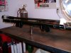
Converting RHD SLC to LHD

The goal is to have no tire to bodywork interference. That means a narrower rather than a wider track. Start with all four lower A-Arms as short as practical with the rod ends screwed nearly all the way in. Bottom them and screw back out a couple of turns. Now install upper A-Arms the same way.

Check Camber. If you have Neg 2-3 degrees, that's great. Now you have that much adjustability. If necessary you can screw out the lowers BUT you give up tire clearance if you do so avoid it if possible and minimize it if necessary. You can now set camber by only changing the upper A-arms rod end length. Hopefully only with the single outboard rod end that is attached to the upright.

In any final setup, the inboard rod ends on the A arms should always be the same number of turns in or out as compared to its mate on the other side. That means at the rear the two lowers are the same and the two tops are the same as compared to the other bottom or top. At the front, again the lowers are the same and the tops are the same. Do not set toe with them.

That's the end goal. Place the A-arms so that the camber can be adjusted with only the outboard rod ends on the upper A-arms. For a street car, your final setting will be neg 1/2 - 3/4 degree. Track only cars will run neg 1 to 2 1/2.

Now that you have the adjustment range accounted for, set camber to 0 on all four corners with 0 toe. Leave the car setup this way until you finish the bodywork and are SURE you have no body to tire interference.

Note: RCR told me that the washers on either side of the A-arms inboard side rodends within U mounts should be centered to get the correct caster, That's how my car is set and it seems fine to me even though I have never measured caster.

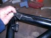
BIG ASS NOTE!!!!!! Always adjust a rod end so that when done with adjustment at LEAST 50% of the threads are screwed into the parent part (A-arm in this case). This does not include jam nut. Measure from outboard face of jam nut to end of threads = 50% of total thread length. In our case given we are working with aluminum, I have made that 60% for peace of mind. This can be a difficult rule to follow. Do it anyway.

This process can be time-consuming and a bit frustrating but if you set up the suspension this way AND THEN place bodywork at least you won't do it the other way around and find you have body to tire issues and not enough suspension adjustment to fix it AFTER you think you have finished body mounting. THAT will be frustrating!
Howard,
In order to set both rear tires at perfect the fore aft distance form the frame and centered on the body I had to move the rear driver wheel about 2mm back, therefore is not perfectly centered do you think that will affect caster much?
Also to get zero camber the threads on all 3 upper arm adjustments get close to 50%, I did measure it closely and was worried for sure , So I agree with Howard , pay close attention , it will take some back and forth adjustment. It took much longer than I thought.
Howard, just curious, what ride height do you use for the track?
 
Blocks for ride height
 

Attachments

  • IMG_5218.jpeg
    IMG_5218.jpeg
    295 KB · Views: 238
  • IMG_5888.jpeg
    IMG_5888.jpeg
    363.2 KB · Views: 229
  • IMG_5889.jpeg
    IMG_5889.jpeg
    451.7 KB · Views: 246

Howard Jones

Supporter
Hector, When I first was putting my car together I called Fran and asked several questions about the setup. Specifically caster, he told me that I centered the rod ends in the "U brackets" then the caster should be as designed. That's what I did. The car steers and tracks fine and I have no reason to change it. However, I have not measured or calculated the caster at either end of the car. I keep thinking someday I will do that but frankly, since the car handles fine other things are higher on the priority list.

I have set the front at 3 3/4 and the rear at 4 1/2. I think that is just about perfect for my car. IF and that's a big if I only ran COTA (very smooth) AND I had a trailer and ramp as well as, driveway, garage entry, etc. that would allow it I might try and run at 3 1/2 and 4 but that's a lot of set up work. Where it is, is pretty much the practical limit.

I used blocks like you have several times for various chassis set up things. In the end I made mine out of 2x3 and 2x4 aluminum tubing and 1/4 inch thick shims. I have since tack welded them all together at 3 3/4 and 4 1/2.

That's pretty much the same place I set mine. Inline with each axle centerline.

I did cut the radius of the rear bodywork wheel arch 3/4 inch effectively allowing the tire 3/4 inch more clearance ahead of the tire at the bottom front. I did this to make it easier to mount the tire but it does also allow the tire to be located as I described as far as the caster is concerned.
 
Last edited:

Howard Jones

Supporter
I went back and reviewed my setup notes and had a rethink about caster. Then I went out and did a quick front caster check. This is done by turning the steering wheel the same amount left then right and measuring camber at each point. Then so that it can be calculated the tire angle used should be 20 degrees in both directions.

for 20 degrees: left camber measurement subtracted from right camber measurement X 1.5 = caster

If you can't get 20 degrees you can use 15 degrees with a multiplication factor of 2.

So 15 degrees L - 15 degrees R X 2.0 = caster

I did this several times and came to the conclusion my SLC is set at about 5 to 5.5 degrees of caster on the front. It was pretty equal on both sides.

Now the question of the rear. I went back and did some reading and in Fred Puhn's book "How to make your car handle" he talked about rear caster on a trailing rod rear suspension. We have double A-arms but the point he makes still makes sense. Race cars usually use rear caster angle adjustment to compensate for and eliminate bump steer at the rear of the car.

When I found that I remembered that I had in fact I had checked the rear bump steer on my SLC and could not produce any. At that, I left the A-arms mounting points alone. Looking at the upright it appears that the center of the top rod-end and the center of the bottom spherical bearing are very close to straight up and down or near 0 caster.

Fred Puhn also said in his book that the rear caster should be set to 0 as a baseline. So there you go.
 

Kyle

Supporter
Well, chalk this up on the list of things that aren’t going well. Sanded the side skirts with 220, cleaned, then laid down carbon fiber with 3m adhesive spray. I then put on the epoxy with a nice coat. Come out an hr later and all of the edges are peeling up. So I had to rip it all off. I’ve seen multiple techniques, I guess I need to maybe try putting the epoxy down first, letting it tack up and then put on the carbon. I don’t know.

61155B16-A6B1-400B-8286-DE164E56E7CC.jpeg
 
OOOOOUUUUUUUUUUUUUCH !!!!!!!!
Try to follow those small tricks to be sure to do a good and safe work ;

1/ have in hand all those necessary things before to start ;
aluminium tape
white light powder named "flox" or "aerosil" ( they are very microscopic bubbles of glass )
Peel ply ( it is asort of "nylon" cloth you will use at the end of lamination
"Kitchen" plastic film or similar film you have on your last pic
bucket of sand !!

2/ Proceed as following
sand with 80 grit ( 220 was not enought to ensure bonding !!) then clean with acetone
prepare carefully the same weight of resin than the weight of clothes of carbon ( it is call lamination 1/1)
Mix in a small separate cup resin hardened with that flox or aerosil until you have a paste ( not too dry)
With a small brush lay this paste onto the edges on top and corners
Onto a flat cardboard lay the carbon fiber on aplastic film and laminate all the plies you want to add ( do not "over" lay too much resin !!)
Carefuly take off ( using the film) this stuff and apply this onto the part taking care not to "splash out too much pastewhen taking off the film from the lamination ; then smoothy lay down from one side to another this lamination ( normaly this time the carbon will stick and stay onto edges and corners !!)
Then place the cut area of peel ply ( with no resin !!) on top of all and gently from one side to another impregnate this nylon clothe so you can
notice where are bubbles ( this film is used to eliminate the excessive resin by himself !!) stop brushing when aspect is nicely done
You can stop at that point but I recommend the following tricks to simulate vacuum process and helps secure bonding ;
2 different methods
1/ place a kitchen film over the wet peel ply trying to avoid too much mess but it's not mandatory as peel ply protect the final aspect
2/ take of your gloves ( normally film is protecting from resin ) and carefully tape with aluminium tape all edges trying to push over the film
Then let cure for 24 hours
Or if the part is more or less flat and can stay on a large piece of wood
1/ place same kitchen film on the wet peel ply
2/ carefully cover with sand all the lamination ( minimum 2or 3 inches thick) and press like children do with castles in seaside !!!!
Then let cure
When all stuff is dry
Take off aluminium tape or sand strip off the film and with pliers "peel"" off the peel ply taking care that you separate this film from the lamination
( normally it comes very easily when pulling )
You will get your part laminated and fully bonded with a very nice external aspect

Apologise for beeing so long but this is the only method to obtain a secure bonding
Hope this helps
 
I went back and reviewed my setup notes and had a rethink about caster. Then I went out and did a quick front caster check. This is done by turning the steering wheel the same amount left then right and measuring camber at each point. Then so that it can be calculated the tire angle used should be 20 degrees in both directions.

for 20 degrees: left camber measurement subtracted from right camber measurement X 1.5 = caster

If you can't get 20 degrees you can use 15 degrees with a multiplication factor of 2.

So 15 degrees L - 15 degrees R X 2.0 = caster

I did this several times and came to the conclusion my SLC is set at about 5 to 5.5 degrees of caster on the front. It was pretty equal on both sides.

Now the question of the rear. I went back and did some reading and in Fred Puhn's book "How to make your car handle" he talked about rear caster on a trailing rod rear suspension. We have double A-arms but the point he makes still makes sense. Race cars usually use rear caster angle adjustment to compensate for and eliminate bump steer at the rear of the car.

When I found that I remembered that I had in fact I had checked the rear bump steer on my SLC and could not produce any. At that, I left the A-arms mounting points alone. Looking at the upright it appears that the center of the top rod-end and the center of the bottom spherical bearing are very close to straight up and down or near 0 caster.

Fred Puhn also said in his book that the rear caster should be set to 0 as a baseline. So there you go.
Thanks Howard, super helpful information, as it turns out i have been going back and forth with the body, and I had to reposition the rear wheel to the center, to make it fit the body perfectly, happy the know that the caster will be fine. Also happy to know that the front caster is also acceptable, since the front tires fit very well the body right now, I m not moving them again. So I stopped counting but I think I spent more than 14 days fine tuning the alignment I think I removed or repositioned every A arm at least 3 times, LOL!! I did learn a lot and can do an alignment in an hour now!!!
Sorry about the hijack Kyle. But this is helpful for your alignment as well. Hopefully you won't have to struggle as much as I did.
 
Well, chalk this up on the list of things that aren’t going well. Sanded the side skirts with 220, cleaned, then laid down carbon fiber with 3m adhesive spray. I then put on the epoxy with a nice coat. Come out an hr later and all of the edges are peeling up. So I had to rip it all off. I’ve seen multiple techniques, I guess I need to maybe try putting the epoxy down first, letting it tack up and then put on the carbon. I don’t know.

View attachment 112482
Kyle,
Don't get discouraged man, you should have seen the mess I made with gorilla glue, epoxy, spray glue, roberts 4002 carpet pad glue, to figure out how to bond insulation and foam together and to aluminum. Sometimes you have to screw up a little, part of the unavoidable learning curve.
 

Howard Jones

Supporter
So I did some more reading and thinking about the rear caster on a double A-arm versus a lower reverse A-arm and trailing links like a GT40. I think I am wrong in the above. With the trailing link GT40 setup everything is moving in arcs front to rear whereas with the double A-arm setup there is no forward/aft movement to change toe like with the GT40. Therefore I believe that setting the upright to straight up and down (0 caster) is more than likely the correct baseline setup. That's probably why my car seems to be fine as it is.

Sorry Kyle I didn't want to leave possibly wrong information without correction.
 
Last edited:

Kyle

Supporter
Can anyone comment on the structural necessity of this cross brace in the rear? Specifically for a street car. Obviously it was put there for a purpose, and provides the only measure of resistance against twisting for the rear of the chassis, but I might have the slide the top attachment bracket more medial.

Also in reference to that same picture, I must be missing something for attachment of the rear clam to the lower frame bracket, the clam stick out at least another 12in away from that bracket. I’m going to be fabricating a new one anyways because I am chopping the rear clam. However, just curious if I’m missing something obvious.
CFA95D74-873A-476A-A77A-661AB2956B66.jpeg
 

Howard Jones

Supporter
Those links are ABSOLUTELY necessary and MUST be installed !!!!!!! They provide the ONLY lateral triangulation to the backside of the rear chassis box. Without them, the welds on the chassis members at the lower corners are forced to try and prevent the entire length of the vertical chassis member from swaying around and finally failing. I cannot stress this enough.

The upper pickup points can be moved inward an inch or two I would think, but the gearbox will limit that. I fould it necessary to weld both the front and back of that tab and ultimately added a second tab to put it double shear.
 

Attachments

  • HPIM2347.JPG
    HPIM2347.JPG
    27.7 KB · Views: 200
  • HPIM2348.JPG
    HPIM2348.JPG
    36.5 KB · Views: 204
  • HPIM2351.JPG
    HPIM2351.JPG
    31.6 KB · Views: 188

Kyle

Supporter
Turns out I don’t need to move the support arms at all, tho it is close. Partially fabricated up the exhaust, the cat will just barely clear the rear end. I will put a double tip on the rear. I’m also going to put an auger style restricter to quiet it down some more. We’ll see how that works. The wide open cut out end will drop down the bottom. At fully bottomed out the axle has about 1/2in clearance.

17981D4A-8C18-421E-A99A-84267090582C.jpeg

77091E68-BE86-4AF6-8738-44DDFE475C94.jpeg
75FF1A48-221B-4F86-94C0-6C191C72E398.jpeg
5983E9C0-C690-453C-9FB9-2074D4917675.jpeg


I also rerouted the rear brakes with nicopp line, there are no joints. Only the T joint and hard to flex joints. The lines will be secured.
0835F179-9E56-4ABC-8E55-9FD33C4F99FF.jpeg
645D13EB-4BD8-44CF-9235-BAD03A6B412C.jpeg
 

Kyle

Supporter
Took a different approach with the carbon fiber, I’ve seen several YouTube videos of this method and I should have just done that to begin with. Basically, epoxy layer on first, wait until the epoxy is tacky, then lay fiber and wait until cured. From there other epoxy layers can be added. This is after my first coat, still need 2-3 more layers of epoxy and to trim. Unfortunately a lot of it will be covered by the nose, but at least it might add some strength.
89D23FA7-EC8D-4DCB-8397-D906D339A0DF.jpeg
C5748A70-037B-4015-AD86-DD03814D6EBD.jpeg
 

Scott

Lifetime Supporter
Can anyone comment on the structural necessity of this cross brace in the rear?

Kyle, as Howard points out this is the only torsional triangulation in the ladder frame part of the chassis. Remove it and you're essentially left with two trapezoids, one at the bell housing and one at this location, with no diagonal bracing. Look at just about any tube structure (e.g., bridge, radio tower, chassis, geodesic sphere, etc.) and you'll see lots of cross bracing / triangles that connect opposite corners. I agree with Howard that the angle is very shallow and you could stiffen things up by moving the tabs on the rear chassis brace as close to the center of the car as the transaxle will allow.

I just finished creating an "X" tube structure in this location to triangulate both sides of the transaxle. In my case the transaxle is a stressed member and the links are connected to it's bulkhead plate, a 1" thick hunk of billet 6061. I will also replace the stock brackets that bolt to the transaxle plate adapter with four dog-bone tubes to create a similar "X" structure.

Stressed Member 21.jpg


I also have a SWAG vertical bandsaw table and the same flaring tool. They are both great and that flaring tool is the only one that I could get to reliably produce a double flare in stainless steel.
 
Last edited:

Kyle

Supporter
Needed to make some big changes. I moved my battery to the back, I just didn’t feel like there was enough room in front. The radiator fans were blasting hot air all over the battery and I really feel like the car will benefit from construction of a duct with this south Florida heat. So that means most of the wiring had to be redone. However this means a shorter run to the battery and no major wires down the middle of the tunnel. These pictures are a couple days old, just finished most of the wiring tonight.
I also finished most the AC. Just have to mount the evaporator, it’s just so bulky and in the way so I have been waiting.

I still have one long brake line to finish that I have been procrastinating on, then I can mount the pedals and bleed the brakes.

ED2F981C-1163-4116-BFC5-FE60A374D3B9.jpeg
46C0C599-CD9C-4E2D-AC10-82F79575A1DE.jpeg
7EA3DBA4-4282-49E5-B63A-B23A2A884FD4.jpeg
 

Kyle

Supporter
I like bouncing around a lot on really any project, I get bored with one task and start another. With that being said the brakes are finally done, tons of leaks from using the POs flare tool originally. Basically had to redo the front lines, the back ones are good. Started fiberglass a surround of sorts for the Holley dash and stereo. They fit in these fiberglass pieces super tight, the plan is I shouldn’t need to attach them in anyway, the tight tolerances you hold everything. Next I will cut out my dash and bond these pieces into place. They look horrible right now but will serve their purpose. Tomorrow I’m going to close out the fuel tank, mount the evaporator, and tie up some loose ends. Still waiting on my flywheel otherwise I could damn near go-kart this thing now.
68F61DCD-68E0-4E5A-B63D-2F92C16A209C.jpeg
8611058C-06F6-4246-BCF6-28A44843F4F8.jpeg
AB6BA722-CD3A-4AEE-A62C-53F5642F7C4C.jpeg
7411A846-C49B-4A0E-A7EC-577E3BBBD05D.jpeg
 

Neil

Supporter
You didn't accidentally mix up a 37 degree flaring tool with a 45 degree flaring tool, did you? It's an easy mistake to make. AN fittings are 37 degree flares.
 

Kyle

Supporter
You didn't accidentally mix up a 37 degree flaring tool with a 45 degree flaring tool, did you? It's an easy mistake to make. AN fittings are 37 degree flares.
I’m not sure to be honest, with the new flare tool everything is working as it should. I used bubble flares for everything. No leaks. Everything is bled and they are really firm.
 
Back
Top