Biessman XLR-917

Patrick:
Those type of couplings are made by Lovejoy, I think if you google it you will find specs.
Also, Detroit Diesel used to mate two V-6 engines together to get the V-12, and there was a coupling between the crankshafts. A little research might get you ahead a little faster.
Good luck on your build
Phil
 
I'm attaching some photos of my STP 917 as it is coming along nicely.

Jack
 

Attachments

  • 100_0333.jpg
    100_0333.jpg
    63.8 KB · Views: 633
  • 100_0411.jpg
    100_0411.jpg
    54.8 KB · Views: 542
  • 100_0402.jpg
    100_0402.jpg
    53.9 KB · Views: 558
  • DSC05230.jpg
    DSC05230.jpg
    52.3 KB · Views: 559
I just have a hard time believing that simply coupling two engines together with two separate ECMs can run/last reliable for use on the track? I know this has been done in the past with drag cars and pulling tractors, but how can this be expected to last? Wouldn't the engine harmonics wreck havoc with the crankshafts?

Dave
 

Randy V

Moderator-Admin
Staff member
Admin
Lifetime Supporter
I just have a hard time believing that simply coupling two engines together with two separate ECMs can run/last reliable for use on the track? I know this has been done in the past with drag cars and pulling tractors, but how can this be expected to last? Wouldn't the engine harmonics wreck havoc with the crankshafts?

Dave

Dave,

I have seen engine/drive couplers made with compliant materials (Steel - Rubber - Steel) that would probably serve to isolate out the harmonics of one crankshaft to another.. Much the same as a rag-joint in your steering linkage does..
 
I understand that those isolators are for industrial applications (i.e. assembly line/ conveyor drive couplings ), but are they really rated for the torque,rpm, and harmonics associated with coupling internal combustion engines?
 
I'm still figuring everything out but it will be two late model Subaru 6cyl, 3.0L engines joined at the crank with a piece I designed. Both engines will be bolted firmly to the chassis with other braces to make the engines one.

So far, I'm planning to run both engines off of one computer with the firing sequences perfectly aligned.[[[[[
I'm hoping a signal to cylinder #1 will fire off both #1"s.]]]]
Keep in mind I'm not an auto mechanic and I'm only using common sence. I do have a Suburu service department and lead mechanic enthusiastically helping me so we should figure something out.

Jack

If you do that & fire both Number '1's at the same time it will sound like two 6cyl engines running synchronised & firing @ 120° intervals, you need to fire one engine 60° later to get the genuine 12 cyl sound, Ive thought about Subarus for another application & would look into hooking them back to back with one motor running anticlockwise & drive taken out of the center just like Mr P*****
 
Jac,
I thought the center drive take-off in a 917 engine is for the fan drive. The clutch and crank flange are still at the back of the engine.
 

Attachments

  • 22072082.MVC046S.JPG
    22072082.MVC046S.JPG
    45.9 KB · Views: 434
Jac,
I thought the center drive take-off in a 917 engine is for the fan drive. The clutch and crank flange are still at the back of the engine.


Nope,
not only for the fan

there was a center drive take off going to an intemediate shaft running to the back of the engine
Zmotor01.jpg

THe flywheel center was offset in relation to the crank center

TOM
 
This build is very cool, and I like the idea for using two subaru engines. I see that your using the corvette suspension, do you mind if I ask where you found the suspension attachment points?
 
This is a link to a program you can try for free. Its called suspension analyzer 2.0. In the program they have the suspension pickup points for a c5 corvette. They are measured in an X,Y,Z coordinate pattern. Dont remember which ones are which but if you have a very basic cad program you can map the suspension pickup points. They are measured inches from centerline. Height above ground plane, and inches forward or aft of axle centerline, ie X,Y,Z. Hope this helps

Bill


Suspension Analyzer
 
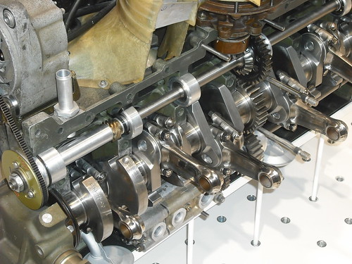
I will be firing the #1 cylinder in the rear engine and the #6 cylinder in the front engine at the same time, and so on, so that a cylinder will fire on opposite sides on each engine. I don't think you can fire one cylinder at a time between the engines, like a 12 cylinder engine, without having two cylinders firing on one side, one after the other, and then two on the other side.

I have a C6 Corvette so I took the measurements off my car. I guess it would have been cheaper to buy a CD! :sad: I have a vintage auto and race car restorer in CT that also runs a vintage racing shop who will do the final suspension set up.

I have a Subaru tuner in CT. that will do the computer, wiring and exhaust work work.

The car will be used for track days and hillclimbs, probably driven by an old fart like me, so hopefully there won't be too much strain on the drive train. There is some flexibility in my adapter as I have used a second drive/flex plate mounted face to face to transfer the front engine's drive to the rear engine.

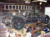
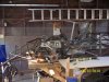
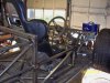
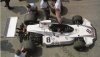
This car will be on YouTube shortly, as soon as I paint the chassis, (Porsche 917/10 Replica), and at Lime Rock on the first weekend of September for their vintage festival and then it will be auctioned off on e-Bay.

This will be the only 917/10 I will build. (when Fran says a tube frame chassis is expensive to build, BELIEVE HIM!) My next project will be a Brabham BT 44B which I will also sell. I am building and selling my dream cars.

I don't know why my latest photos whouldn't upload and I'm too tired to find ouT. Here is my next project photo.

Jack
 

Attachments

  • BT 44B high.jpg
    BT 44B high.jpg
    51.6 KB · Views: 339
Jac Mac,

I had looked at 30 and 60 degrees. I'll have to look at 120 and see how that works out.

jack

Nothings ever simple is it..
The porsche has paired rods on three journals @ either half of the crank, the Subaru IIRC has two seperate rod journals @ 180° for each pair of cyls along the crank.
The porsche crank is the same as a six cyl in-line crank in layout, but with the PTO Gear in the middle..

DWG _Might:):) help explain...
 
Last edited:
Back
Top