Brett's RS GTD

Randy V

Moderator-Admin
Staff member
Admin
Lifetime Supporter
Perfect illustration Bill :thumbsup: that is exactly the point I was trying to get across..

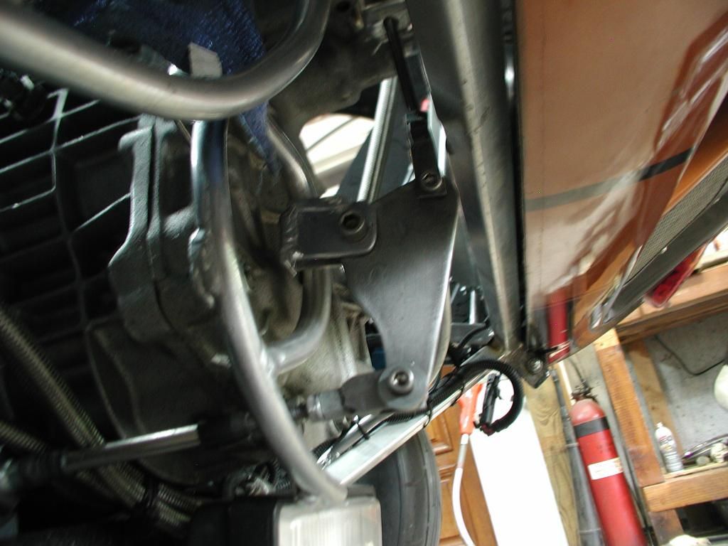
I would use a bearing or bushing of some sort at the pivot point. You can use just a bolt through metal to experiment on getting the right mounting points for the cable end and the rod that will connect to the shift mechanism.
 
Bill,
Thanks, got that. It's the 0 position that maybe I am over thinking i.e how to make this piece/area up.

Would you just drill the arm/crank and let it rotate on a shanked bolt, or would you put a bearing in there? If so what type of bearing would you recommend. Thanks much
 
Brett,
I used a bell crank with my shifter. It works off the nut and bolt arrangement and rod ends to finish off. It works well for me. You just have to make a few decisions. Since this is the neutral gate it doesn't need to be heavy duty. Loads are light and unless you are just slaming gears it doesn't need to be overbuilt. I would think all you need to consider is tolerances and not let it be sloppy or too tight. I used nylocks and that was it.
P1010251_zps921b2dac.jpg

As you can see I used three types of connectors. Just stuff around the shop.
If you want it to be real pretty then go for a bearing. It just has to accomodate the bolt that will hold it in place. Any size will work and should be found at any hardware shop. probably in the lawnmower parts section or something similar. The guys in the shop should be able to find what you need.

Bill
 
Awesome build log Brett. I just procrastinated a good 30 minutes at the start of my work day. This has inspired me to get my act together and order some parts for our project.
 
So it's only taken me about 6 weeks to get round to ordering some electrical bits! and also find some time to be able to go to the garage!

Managed to get a few hours and have installed the new starter relay loop and relays for the lower spots and the new fuse box, which is split 50:50 switched live/perm live.

The photo below shows the start relays. Looking at the way things were laid out it appeared that load would go through the ignition switch, even though relays are installed, the feed for them was switched through the ignition, so not happy with this, I've put a loop in that sends the power through fused relays but uses the same power to switch the relays on (via the ignition switch)


Ignition switch protection relays by Brett-GT40, on Flickr
 
Got some time today (a rare occurence) and we have - working wipers yay!

Now the good news the switch design I borrowed from somebody else works using an old Lucas 4 position rotary with a push function (that will be the wash)

So click clockwise. Low speed - good; high speed - good. Go back to start position

Click anticlockwise and all good and then, err, damn it doesn't work. Suddenly about 60 secs later ping it goes again. So the intermittent works, but clearly 60 secs is WAY too long. So I'll be ordering a different delay relay VWP on Tuesday and then having to change the config round. The relay I have is an old Skoda one off eBay, never mind


Untitled by Brett-GT40, on Flickr
 
Sadly longer in reality than I probably know Andy :(

Will try and devote more time with it over the autumn winter to get things going. Just happy to see certain things working like the wipers and the protection circuit I decided to put in.

Need to get some help gassing all the lights in the front clip before the chill comes so I can make progress then :)
 
PS it's the little things that take up time, for instance, where I have decided to run my loom now means that I need to take apart three of the connectors and elongate the wires so that it all runs properly. Not much inreality probably 18 wires intotal, but it will mean an afternoons work
 
So question for you clever types. Any thoughts on how I could take the switch on the left that has a half round connection and use the knob on the right that is designed for a switch with a hex piece? Both are 1/4". I want to do it to try and keep some form of consistent looking switch gear. As the LR Series one knobs are no longer available, I have opted for some TR6 knobs, like these: 'F' Knob for Hexagon Shaft - Switches from Holden Vintage & Classic


Untitled by Brett-GT40, on Flickr
 
you could fit a wedge into that knob...if the round part fits you could fill up the other part with a wedge made from something the same shape as that nut-shaped hole, for example a very high nut and cut that in half then you have 2 wedge's :D
maybe you can find something better material than iron in the same shape, say nylon or so?
 
ow...was thinking perhaps you could buy some 2-component glue/filler/plastic and put some in that knob and then put it on the switch and let it dry, don't know how slick? that iron part is otherwise you could put something on that too so you can always get the knob of again.
 
Managed to get a wee bit of time today and got a few things sorted.

A new delay relayhas been put in and works, so I now have intermittent wipers :thumbsup:

Spliced in the old Lucas hazard switch and got it all working :thumbsup:

Figured out again that the people who built the loom were muppets. The switched live wire for the reverse light didn't even connect in. One jumper wire later and it works. Just need to try and connect into the gearbox switch somehow. I reckon I will have to go to a breakers to get the specific connection for the Audi box
 
Brett, I'd be interested in seeing some pix of your cable shifter mechanisms, both ends (box and stick), I am thinking of tackling one, I have the cables and a rough idea, however I'd like to know about yours. Do you feel it gives good tight selection? K
 
So I have been doing bits of work here and there. There is now a big white board up on the wall of the garage with tasks to cross off, some are slowly being wiped off. Also a friend is coming round after work once a week to give me a bot more impetous.

So pics attached of stuff you can see (you can't really show circuits being tested).

Top of the box that willl house the fuses and now also the EWP controller. The light grey is where i had a concentration lapse moment and drilled all the mounting holes in the wrong place and rather than buy a new box, just filled with bumper plastic repair.

12272467805_bbe46021ba_z.jpg


The next is the fuel filler close off panel staring to go in place

12273028206_3e688d121c_z.jpg
 
Well, the Thursday evenings are starting to pay off, as I feel like I am slowly making progress again. It's quite hard to motivate yourself after so long.

I think this is a major milestone for me... Effectively there is another hardpoint to work from now with one set of relays (the original that came with the loom; the adds are being placed elsewhere) and the fuses (including the new block) mounted. It now means I can start to determine other wire lengths for the additional circuits and start to final fix the main loom into place. I think it looks quite smart. Thinking about it, I should have dropped the dash in so I could take a photo too. I've also final fixed the fuel hose close of panel and access hatch.


Untitled by Brett-GT40, on Flickr

The relays have been designed to come out for servicing if needed. One end is a semi hole that pushes onto a grommet that is secured. The end you can see willl undo and the relays will drop out (ignore the flange nut, that will become a wingnut)


Untitled by Brett-GT40, on Flickr

and... I've also cutback and soldered on some wires for the Reverse switch. The car must be wondering who this person is working on it :laugh:


Untitled by Brett-GT40, on Flickr
 
Back
Top