
You are using an out of date browser. It may not display this or other websites correctly.
You should upgrade or use an alternative browser.
You should upgrade or use an alternative browser.
Brett's RS GTD
- Thread starter brettmcc
- Start date
Brett James-McCall
Moderator
Keith, they are genuine... but the loom I have has different coloured wires to what Mick has told me (and what is on the loom sheet). I bought it a while back, so I think I may have an older loom, but newer loom sheet. Mick and Adam will sort me out (and also probably tell me how stupid I am (but there's nothing new there either ") )
)
)
Brett James-McCall
Moderator
I finally managed to get a few hours in over the past weekends and today (literally only a few), the first in months.
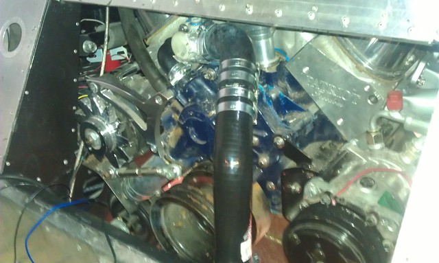
I managed to unpick part of the front loom and move some wires back into the cabin due to where I have placed some of my controls etc. I also managed to choose a location to punch holes through and push the loom through the bulkheads. This required me to undo all the connectors and then having to reassemble.
Also managed to get a small mount quickly made for the horn, so it's just another little thing ticked off the list.
However, the electrical gremlins are still occuring, see my post in electrics. I can't seem to get the light relays to pick.
IMAG0407 by Brett-GT40, on Flickr
Brett James-McCall
Moderator
So two days in a row on the car, which probably means I won't be allowed out to play on it until Spring judging by recent work rate.
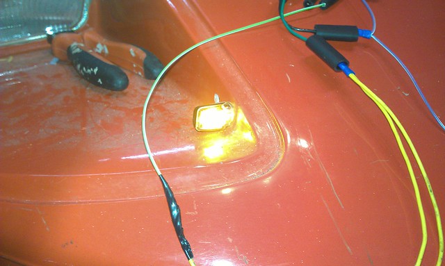
However, today I seem to have fixed the lighting relay issue, if you haven't seen the other thread here's a headlight with a working bulb :idea:
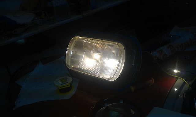
IMAG0412 by Brett-GT40, on Flickr
For anyone wondering, it's a Renault 12 headlamp
I then managed to finish of making some hose joiners and got the final pieces of the coolant lines run :thumbsup:
IMAG0413 by Brett-GT40, on Flickr
More things ticked off - there's a glimmer at the end of the IVA tunnel!
However, today I seem to have fixed the lighting relay issue, if you haven't seen the other thread here's a headlight with a working bulb :idea:
IMAG0412 by Brett-GT40, on Flickr
For anyone wondering, it's a Renault 12 headlamp
I then managed to finish of making some hose joiners and got the final pieces of the coolant lines run :thumbsup:
IMAG0413 by Brett-GT40, on Flickr
More things ticked off - there's a glimmer at the end of the IVA tunnel!
Brett James-McCall
Moderator
Oh my three days in a row... well a few hours this evening anyway and it was rather productive! A friend came over and we had a go at various things.
Firstly rewiring the indicator relay wiring to accept the the Electronic Relay I had decided to put in. Please to say it worked and the little front indicators I got look a treat.
IMAG0415 by Brett-GT40, on Flickr
We'll figure out how to wire in in the NOS Lucas Hazard switch soon.
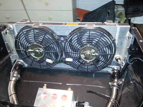
We also wired in the fans and shorted them to check they were working. All good and another major milestone for me after so long on this build! The only thing that has come of it, is the thermostat I bought thinking it would be quite nice to have will go. I bought one of the Revotec adjustable units, but now on reflection I will just go back to a 95/86 or a 88/79 standard unit - what do people suggest?
Here's the fans, WHOOP
GT40 Replica Build - Working Fans - YouTube
(Can someone also tell me how to embed You Tube into the posting, as I couldn't get it to work...)
Firstly rewiring the indicator relay wiring to accept the the Electronic Relay I had decided to put in. Please to say it worked and the little front indicators I got look a treat.
IMAG0415 by Brett-GT40, on Flickr
We'll figure out how to wire in in the NOS Lucas Hazard switch soon.
We also wired in the fans and shorted them to check they were working. All good and another major milestone for me after so long on this build! The only thing that has come of it, is the thermostat I bought thinking it would be quite nice to have will go. I bought one of the Revotec adjustable units, but now on reflection I will just go back to a 95/86 or a 88/79 standard unit - what do people suggest?
Here's the fans, WHOOP
GT40 Replica Build - Working Fans - YouTube
(Can someone also tell me how to embed You Tube into the posting, as I couldn't get it to work...)
Brett James-McCall
Moderator
Well more time in the garge today and the task - replacing the radiator mounts...
So Rad out
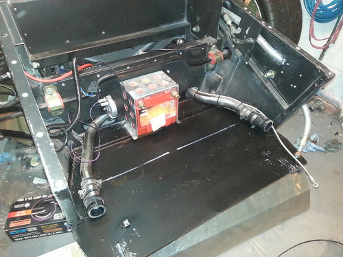
rad bay by Brett-GT40, on Flickr
New Anti-Vibration mounts in
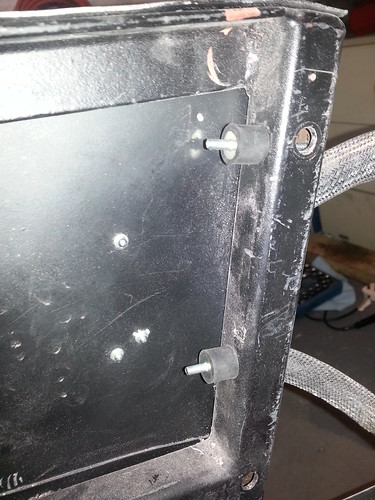
vibration mount by Brett-GT40, on Flickr
I also finally got round to making the lower fan mounts as well along with a new thermostat
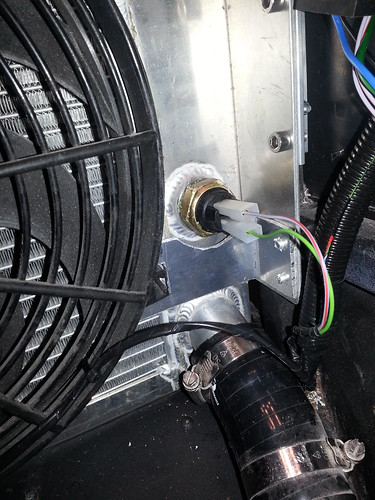
offside lower fan mount by Brett-GT40, on Flickr
Angle cut and all mounted back in... and that was the day done
rad by Brett-GT40, on Flickr
So Rad out
rad bay by Brett-GT40, on Flickr
New Anti-Vibration mounts in
vibration mount by Brett-GT40, on Flickr
I also finally got round to making the lower fan mounts as well along with a new thermostat
offside lower fan mount by Brett-GT40, on Flickr
Angle cut and all mounted back in... and that was the day done
rad by Brett-GT40, on Flickr
Excellant work & progress Brett - nearly there. So what's stopping you putting in some fuel & oils & firing her up!
Rgds,
Andy
Rgds,
Andy
Brett James-McCall
Moderator
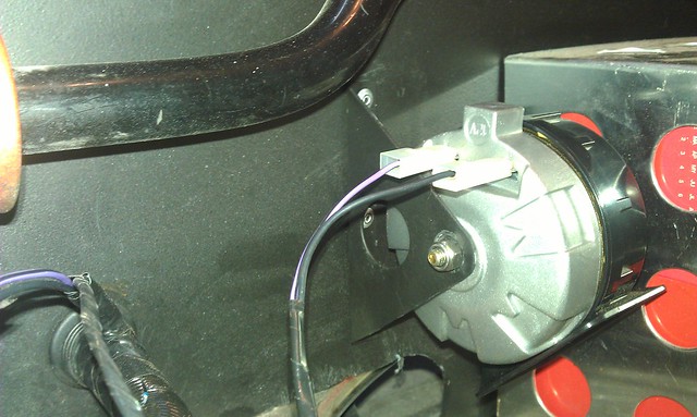
So Andy, I still have to finish doing the final wiring on engine, especially the HT leads, the MSD unit and the Craig Davies WP and controller. Once that is done then probably nothing, except....
I'd prefer to get the other systems sorted and out of the way and tested first. So still need to finish doing the wipers and HVAC (I at least want to test the heat when I fire up the engine, the AC can wait until after IVA) and install a couple of circuits I need to put in (elec mirrors etc). Oh and I've decided to order a new alternator as well.
I'd prefer to get the other systems sorted and out of the way and tested first. So still need to finish doing the wipers and HVAC (I at least want to test the heat when I fire up the engine, the AC can wait until after IVA) and install a couple of circuits I need to put in (elec mirrors etc). Oh and I've decided to order a new alternator as well.
Brett James-McCall
Moderator
Not much done this weekend; I spent more time on a different kind of electrics, the house variety...
For the small amount of time I had, I remounted the MSD 6AL unit I have and ran in the wire for the tacho (which still has to be connected up). I also mounted the blaster coil. I guess it is another set of small things to tick off, at least some progress is better than no progress
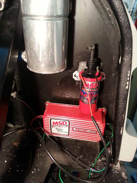
Untitled by Brett-GT40, on Flickr
For the small amount of time I had, I remounted the MSD 6AL unit I have and ran in the wire for the tacho (which still has to be connected up). I also mounted the blaster coil. I guess it is another set of small things to tick off, at least some progress is better than no progress
Untitled by Brett-GT40, on Flickr
Brett James-McCall
Moderator
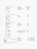
So a question in another thread reminded me that I am currently not that happy with my cross gate shifting and what I have done. So a v2 is coming (fore and aft are fine).
I was thinking of making a L arm similar to other mechanisms I have seen. My qyestion would be. Would people put a bearing where I have put A. If so what and how assuming the arm would be cut from late ally and have to be raised slightly. Thanks
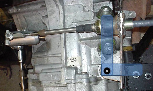
DSC02002_lever by Brett-GT40, on Flickr
I was thinking of making a L arm similar to other mechanisms I have seen. My qyestion would be. Would people put a bearing where I have put A. If so what and how assuming the arm would be cut from late ally and have to be raised slightly. Thanks
DSC02002_lever by Brett-GT40, on Flickr
Brett -
Not sure why you would have that mount anything other than solid. Considering that these cable ends are meant to have roughly 30 degrees total misalignment - it should be just fine.
If you are ot happy with the performance of the cable system, watch the cable closely to see if it moves at all while moving the shifter through the range of gears. You may find that you need to use Adel clamps on the cable in 2 or 3 places in its run between the gear selector and the gearbox itself.. Once you lock the cable down, you will be amazed at the better performance of the entire package..
Brett James-McCall
Moderator
Randy, they are fixed. I am not getting enough movement across the gate for my liking, hence the change. It is tied down in places, but I may need to do it further. Will have another look. Thanks
Brett,
I can't tell from your pic if the mount that supports your cable is mounted on bothsides of the cable. If not add that to the mount. Also add some vertical bracing as it could be flexing with any resistance that you are feeling while shifting. If it is flexing then you will have less of an angle for the end to travel through and thus drag or resistance.
Bill
Brett James-McCall
Moderator
Bill, it is fixed on the other, I'll take a pic. The issue is I can't seem to get enough travel for the mechanism. Having the ram it up tightly against the edge of the shifter unit. I have a Brandtwood one through Fran. If anyone has any adjustment tips, that woudl also be great
Randy, they are fixed. I am not getting enough movement across the gate for my liking, hence the change. It is tied down in places, but I may need to do it further. Will have another look. Thanks
I see.. Well okay then.. Just remember that any movement in that cable between the gear selector and the shifting mechanism is movement that you LOSE from the actual cable itself as it is connected to the shifting machanism.
You may need to connect an intermediate bellcrank in order to adjust the throw of the neutral gate since I know the Brandwood shifter itself does not have that sort of adjustment (well mine doesn't as far as I recall)..
Brett James-McCall
Moderator
Yeah. I guess that's back to my original question. If I use point A on the diagram as the fixing point - what's the best way to make this? Would I need a bearing?
I must be really dense today as I am not understanding what you really want to do.
Your drawing overlaid on the image and question about a bearing at "A", would seem that you are not solidly anchoring the cable jacket. That jacket MUST be anchored solidly. If you want in increase or decrease the movement of the transmission shifter shaft, you would have this bellcrank as an intermediate connection point for the cable.
IE the cable would be connected to the bellcrank and somewhere between the point where the cable is connected and the pivot point, would have yet another link that would then connect that bellcrank to the transmission shifter shaft.
If I had some means of drawing a picture of this on my iPad, I would.. Sorry..
Brett James-McCall
Moderator
Sorry, my bad for maybe not explaining enough.
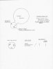
You can see the current setup maybe a little clearer here (though I've changed the back/front to underneath now)
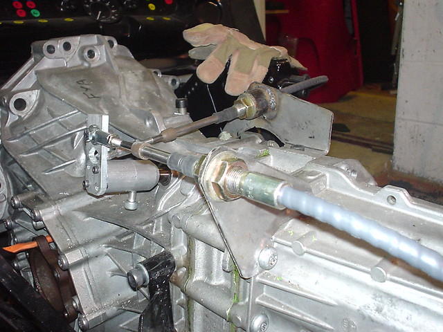
DSC02006 by Brett-GT40, on Flickr
What I am proposing to do is to remove the cross gate bracket and change it's position so that it connects to a bell crank. The bell crank would be fixed into the gearbox in a Lconfiguration similar to the blue overlay in the original picture. It would bolt into the gearbox where I have marked A.
I am asking what is the best way to make the bell crank, would you just fabricate say out of aly, drill and then bolt; or would you fabricate the arm and put a bearing in? Due to the position of the bolt hole the arm would have to be raised off the gearbox from clearance.
You can see the current setup maybe a little clearer here (though I've changed the back/front to underneath now)
DSC02006 by Brett-GT40, on Flickr
What I am proposing to do is to remove the cross gate bracket and change it's position so that it connects to a bell crank. The bell crank would be fixed into the gearbox in a Lconfiguration similar to the blue overlay in the original picture. It would bolt into the gearbox where I have marked A.
I am asking what is the best way to make the bell crank, would you just fabricate say out of aly, drill and then bolt; or would you fabricate the arm and put a bearing in? Due to the position of the bolt hole the arm would have to be raised off the gearbox from clearance.
Brett,
It sounds like you need a variation of the bell crank. To extend your reach of the cable, both cable connection and shift connection should be on the same side of the arm, sort of like this:
0-----1------2
The 0 is the mounting of the new arm(your bearing). 1 is where the cable will tie in (at right angle) and 2 is where the new arm to the shifter mounts. This will extend your cable throw and shorten the movement of the shifter itself. Just have to play with the distances til you get the feel you want. You don't need a true bell crank unless you are changing the direction of the force aplied. Google or Bing bell crank.
Bill
Similar threads
- Replies
- 2
- Views
- 570