Keith's RCR GT40 Mk I Build

Keith

Lifetime Supporter
Wheel alignment and set-up, Part 1:
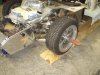
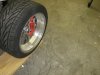
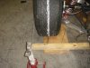
This weekend I installed the wheels and tires and put it on the floor for the first time. My first impression was "wow that is low".
To make a level platform to do the alignment I purchased two ten foot long 2 x12's and marked them with 95 inch center lines to approximate the wheel base. I marked two 20 degree reference lines from the inside portion on each 2 x12 at the front wheel location so that I could use my snap-on alignment gauges to measure caster on the front. After shimming the 2 x12's to get them level side to side and front to rear I set the car down on the them and again I said "wow is that low". I did an initial once over on each wheel with a carpenters level to roughly get camber and caster set and I "eye balled" the toe to get that close.
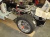
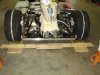
I placed four 60 lb bags of "play sand" ( one front, one rear and one on each fuel tank) simulate the weight of the body and interior. The Gt 40 chassis does not lend itself to a triangular measurement to make the rear axles perpendicular to the center line of the chassis. After some close measurements I found that the front edge of the chassis cowl (the part the dash sits on) is well within 1/32nd of and inch to being perpendicular with the chassis (thank you Fran!) so I used that to set the front to rear position of each rear axle using the trailing arms for the adjustment (once this is set you would only use one trailing arm to make the caster adjustment to keep the location the same side to side).
Here are a few observations to help other RCR owners in the future:

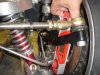
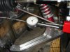
1. The coilovers have twelve threads per inch so twelve turns of the adjustment collar will bring the chassis up or down approxilately an inch.

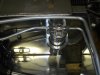
2.Turning the upper ball joint one complete revolution will change camber approximately 1/4 degree. To get a finer adjustment you have to use the rod ends on the inside of the upper control arm, approximately 1/8th degree per turn or 1/16 degree per half turn.

3. Caster changes approximately 1/2 degree for every two washers moved on the upper control arm.

4. Set/check your ride height several times during the process as small changes in ride height can make changes in camber ( both front and rear)

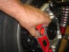
5. When making adjustments to the front upper control arm you do not have to remove the wheel/tire. Just lift the front with a floor jack to get the weight off (coil over spring is loose), remove the castle nut ftom the upper ball joint and the arm can be removed/adjusted. The tire /suspension will just stay on the floor.

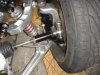
The suspension is very adjustable. I experimented with the max range of caster on the front and was able to change it from +8 to -3 caster with just the washers. You can easily get 3 degrees of camber change with just the upper ball joint alone. The rear has even more adjustment. (Thank you Fran)
As my car is intended more for street use I set it as follows:

LF RF
Ride height 4.5 inches 4.5 inches
Camber -0.5 -.05
Caster +3.5 +3.5
Toe in 1/16 in 1/16

LR RR
Ride height 4.75 inches 4.75 inches
Camber -0.75 -0.75
Caster +5 +5
Toe in 1/32 in 1/32

Keith
 

Attachments

  • GT40 180.jpg
    GT40 180.jpg
    154.3 KB · Views: 1,094
  • GT40 181.jpg
    GT40 181.jpg
    151.2 KB · Views: 1,402

Fran Hall RCR

GT40s Sponsor
Keith..

I had to put my shades on to look at your pics....

Thank you for your description...I am sure many others will enjoy the read, and find it useful.
 

Keith

Lifetime Supporter
Wheel alignment and set-up Part 2
After looking at my wheel alignment post one of my co-workers asked if there was way that a home builder could do an accurate alignment without the cost of a caster/camber gauge.
I spent some time last evening checking the alignment with with a small electronic carpenters level with a magnetic base (less than $40) and I was pleasantly surprised at the accuracy.
I checked the camber by placing the magnetic base of the level on the end of the knock off hub five times. Between each measurement I would roll the chassis back and then forward on the 2x12's and push down on the chassis to let the springs return it to the correct ride heigth. Every time the level was within 0.1 degree of what the Snap-on gauges indicated (taking into account that the level was vertical so the reading was 90 degrees minus the 89.5 indicated on the level or -0.5 degrees).
I measured the caster by placing the level on the back side of the rear upright and the front side of the front upright (it has to be held in place as the magnet does not work as well on the aluminum). In this case the caster was within 0.2 degrees of the reading I had from the other gauge (I believe this would have more to do with the tolerance/location of the holes that the ball joints pass thru in relation to the center of the upright, and the tolerance of the ball joints themselves, than the accuracy of the level).
From the measurements I took, I believe that given a good level surface a home builder can do an accurate alignment with an electronic level.
Keith
 

Attachments

  • GT40 184.jpg
    GT40 184.jpg
    140.6 KB · Views: 733
  • GT40 185.jpg
    GT40 185.jpg
    145.2 KB · Views: 855
  • GT40 186.jpg
    GT40 186.jpg
    137.1 KB · Views: 685
  • GT40 187.jpg
    GT40 187.jpg
    136.6 KB · Views: 704
Last edited:

Keith

Lifetime Supporter
Wheel alignment and set-up Part 3
Installing the bump steer kit was pretty straight forward. The first step in the process was to get the steering rack in the center of it's travel. To do this I installed the steering wheel and placed a piece of tape at the top center of the wheel. It appears that the rack is approximately three and a quarter turns lock (left) to lock (right) by trial and error I just kept moving the steering wheel on the quick release hub until I had the wheel in the center of travel of the rack (approximately 1.6 turns left and 1.6 turns right from center). In the case of my car the rods on the rack measured off the chassis to the end of the arm were approximately nine inches on the right and eight on the left with the rack in the "centered" position.
The pins that go thru the steering arms did not have the correct taper to match the tapered holes in the arm. I modified the pins in the lathe to match the arm (I would guess that this could be done in a drill press with a file if close measurements and proper care were taken).
Both aluminum sleeves were shortened 3/8 inch on the outboard end to accomodate the rod end jam nut. The left hand sleeve was shortened 3/8 inch on the rack end and the threads were chased with a 14mm x1.5 tap (the threads were anodized and felt like they were binding so I ran a tap down the hole and added some grease to keep the aluminum from galling). As the right side rod was an inch longer than the left I cut 3/4 inch from the right side sleeve and chased the threads with a tap. On the right side I had to cut 3/8 inch off the rod end and 3/4 inch off the rod on the rack to get enough adjustment to properly set the toe in.
To set the bump steer I set up a magnetic base dial indicator on the brake rotor over to the chassis. I used a floor jack and sand bags (plus my weight applied with my knees) to move the suspension thru four inches of travel (two inches extension and two inches of compression). By moving the spacers from one side of the rod end to the other (this is really a trial and error exercise) I was able the get the readings within .005 on the first inch of travel up and down. On two inches up and two inches down (four inches total) I was able to get within .020 on the left and .026 on the right. This is where I stopped as it is a really frustrating process (what makes things better at two inches makes things worse at one inch etc).
All in all a good evenings work, Keith
 

Attachments

  • GT40 193.jpg
    GT40 193.jpg
    146.8 KB · Views: 761
  • GT40 188.jpg
    GT40 188.jpg
    131.2 KB · Views: 724
  • GT40 191.jpg
    GT40 191.jpg
    150.8 KB · Views: 745
  • GT40 192.jpg
    GT40 192.jpg
    141.4 KB · Views: 806
  • GT40 190.jpg
    GT40 190.jpg
    146.4 KB · Views: 819

Randy V

Moderator-Admin
Staff member
Admin
Lifetime Supporter
To set the bump steer I set up a magnetic base dial indicator on the brake rotor over to the chassis. I used a floor jack and sand bags (plus my weight applied with my knees) to move the suspension thru four inches of travel (two inches extension and two inches of compression).

I'm curious why the sandbags were needed?
 

Keith

Lifetime Supporter
I had to have a way to compress the suspension. I would add the bags plus my weight to compress then use the floor jack to lift.
If I were doing it again I would take the top bolt out of the shock mounts then just use the jack to raise and lower the suspension thru it's travel.
Keith
 

Chuck

Supporter
Keith:

Really good info. I started this project then stopped when I confronted the problems you addressed.

Rather than shave down the pin, I wonder if one could ream out the hole on the steering arm? I had that problem on the Cobra and the manufacturer graciously loaned me a taper reamer. Wish I still had it. Looks like an item not readily available at the local hardware store.

I note you chased the threads in the aluminum sleeves. I found that a bolt would go in half way and then seemed to jam up. When I looked carefully inside there seemed to be a change in the angle of the threads. It was almost as though it was intended to jam to make it secure. Not knowing for sure what the intended design was I backed off until I could get some answers. Both of the aluminum sleeves had the same design. The outboard side threads worked just fine and did not have the variation in the threads as on the inboard side.

I am guessing that you simply chased the threads to make it symmetrical all the way.

Your GT is really coming along nicely.

Chuck
 

Randy V

Moderator-Admin
Staff member
Admin
Lifetime Supporter
I had to have a way to compress the suspension. I would add the bags plus my weight to compress then use the floor jack to lift.
If I were doing it again I would take the top bolt out of the shock mounts then just use the jack to raise and lower the suspension thru it's travel.
Keith

Okay - I see... I just spin the adjuster all the way to the end of the shock and that works too..
 

Keith

Lifetime Supporter
Chuck,
I looked at the pin taper issue the same way you did. My first choice was to ream the hole, however, I would have had to have a reamer ground to that size as I could not find anything like it. Recutting the pin seemed to be the correct way to go.
The sleeve issue was the same too, it would go on five or six turns then bind. As I did not want to take a chance om galling the threads I chased them with a tap.
Keith
 

Keith

Lifetime Supporter
Denny,
Thank you for the kind words, and thanks again for your help with the parts. I have been working on the sway bar system. I should be posting something in the near future.
Keith
 

Keith

Lifetime Supporter
Wheel alignment and set-up Part 4:
I finished the wheel alignment this weekend. I did it the "old fashoned way" with a scribe bar.
First I set up two parallel string lines with masons string tied to jack stands on each side of the car with the string approximately 3.5 inches from the chassis on each side making sure to measure the distance between the strings at the front and rear of the car several times to ensure that the lines were parallel. With these lines in place you can measure from the front and rear outside edge of each wheel rim to the string to get the wheels/tires parallel to the chassis as a starting point for setting the toe-in.

I built a home-made scribe bar from a 2x4 and some 1/8 inch steel rod. I chalked the center of each tire with white tire marker and scribed a line in the chalk mark by rotating the tire/wheel. The scribe bar was then set behind the wheels, the pointers were set to the center of each scribe line then moved to the front of the wheel to measure the toe/in/out. The fronts were set to 1/16 in (1/8 total) and the rears to 1/32 in (1/16 total). The process was repeated several times to check and re-check.
The only change to the alignment from my first post is the ride height. After discussions with Fran I was inclined to follow his advice and raise the rear ride height to 5.5 inches. The system Fran has designed provides for very precise adjustment. I am very pleased at how the alignment came out.

A few more observations that may help RCR owners in the future:
1. The tow adjustment for the rear is best accomplished with the rear most outer lower rod end.
2. One full turn of this rod end is approximately 1/8 inch of toe (one half turn is 1/16 inch).
3. The adjustment of this rod end effects camber, so camber needs to be re-adjusted after each change prior to reading the toe in as in this case one effects the other (in my case moving the toe 1/4 inch in changed the camber 1/2 degree negative).

I spent another hour or so re-checking every nut and bolt, making sure everything that needed thred locker had thread locker, and installing the cotter pins.
Keith
 

Attachments

  • GT40 198.jpg
    GT40 198.jpg
    136.7 KB · Views: 621
  • GT40 195.jpg
    GT40 195.jpg
    150.3 KB · Views: 648
  • GT40 199.jpg
    GT40 199.jpg
    153.2 KB · Views: 829

Keith

Lifetime Supporter
I followed Chuck and Ryan's lead and had Hot Rod Air fabricate a new line so that the trinary switch pointed down. Along with the new line I purchased one of their polished aluminum brackets for the reciever/drier. I enlarged the center hole in the bracket so it would fit the reciever/drier with a 1/2 inch wide piece of radiator hose around it as insulation.
It made for a very good looking and secure instillation.
Keith
 

Attachments

  • GT40 197.jpg
    GT40 197.jpg
    136.1 KB · Views: 890
Wheel alignment and set-up Part 3
This is where I stopped as it is a really frustrating process (what makes things better at two inches makes things worse at one inch etc).
All in all a good evenings work, Keith

Keith great job on bump steer.
One thought you may consider is, with the changes you made you are just adressing one issue.
The height of the rod leverage point, with this of course the length of the rod is changing also a bit ( but not much) and you are stuck with a given lenght because you have to keep the total toe in correct. But may be it just works even better if the total lenght of the rod would be different and therefore the action points are moving more parallel to each other.
I would just give it a try and shorten the rod as much as possible with the sleeve ( or lengthen it as much as possible) and then do the measurements again. Still keep your steering rack centered to keep the inner point and don´t care about the toe in or out . just do the measurements in this position, if you would find out that a longer or shorter rod lenght gives you lesser bump steer, you could than change the bending of the steering arm inward or outward to the desired position ( and rod length) and readjust your toe in.
Hope you are able to understand it, because this is the limit of my english.

TOM
 

Keith

Lifetime Supporter
Keith great job on bump steer.
One thought you may consider is, with the changes you made you are just adressing one issue.
The height of the rod leverage point, with this of course the length of the rod is changing also a bit ( but not much) and you are stuck with a given lenght because you have to keep the total toe in correct. But may be it just works even better if the total lenght of the rod would be different and therefore the action points are moving more parallel to each other.
I would just give it a try and shorten the rod as much as possible with the sleeve ( or lengthen it as much as possible) and then do the measurements again. Still keep your steering rack centered to keep the inner point and don´t care about the toe in or out . just do the measurements in this position, if you would find out that a longer or shorter rod lenght gives you lesser bump steer, you could than change the bending of the steering arm inward or outward to the desired position ( and rod length) and readjust your toe in.
Hope you are able to understand it, because this is the limit of my english.

TOM

Tom,
I had not considered that. In the past working on race cars, I was always taught that the closer the tie rod angle to the angle of the lower control the less the effect of bump steer on the system. In this case the right side tie rod angle is greater than the left side as the tie rod is shorter. Good food for thought.........I am sure there is room for improvement here.
Thank you, Keith
 

Chuck

Supporter
Keith:

That aluminum bracket for the AC drier looks good. Much more substatial than the stock straps.
 
Back
Top