
You are using an out of date browser. It may not display this or other websites correctly.
You should upgrade or use an alternative browser.
You should upgrade or use an alternative browser.
Hi Larry,
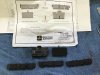
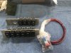
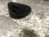
I ordered the items shown on the schematic from Mouser Electronics. As you know, the steering column is from an 1999 Olds Intrigue. I've attached photos of the parts.
Hope this helps


I ordered the items shown on the schematic from Mouser Electronics. As you know, the steering column is from an 1999 Olds Intrigue. I've attached photos of the parts.
Hope this helps
Thanks Kurtiss
The Crazy Californian and his wife on the U.S. Tour made it home! The trip to Georgia and back was fantastic. We left Palmdale, CA, and went straight to H’s in Buford, GA. Working with H for two weeks was a fun and rewarding experience and will greatly help my future fabrication needs. On the way back from Georgia, we first stopped in Houston to visit my daughter Eryn and her beautiful family plus we saw Rufus and good friend Marc. Then drove to Phoenix and spent a few days visiting my mother and saw Ken and Danelle Tanner (GT-R builders). Lastly drove to Yuma to visit my wife's family before heading home.
We traveled 5840 miles towing a wide track, 22’ enclosed trailer. There were a few “white knuckle” moments when driving down Road-Work narrowed highways but it was great getting away after being sheltered at home for 6 months due to COVID 19.
Thanks to H, I am months ahead in building my car. Still lots of finishing work to do before paint or interior.
Kurtiss wow that seems like one heck of a trip good for you and your wife to get out and enjoy the open road in these crazy times. Kurtiss did you get the push button starter switch from Racewire Solutions I got the switches and switch plates but they sent me a kill switch in lieu of the start button
Attachments
Kurtiss I forgot to ask how is Rufus doing he hasn’t posted in a long while
Hi Larry,
I used the Digital Guard Dawg Start Button available from Summit Racing. If you need more switches, different covers or parts, go to https://www.otrattw.net.
Rufus is doing great and his GT-R is coming along quickly. He's working on the body and getting it ready for paint.
K
I used the Digital Guard Dawg Start Button available from Summit Racing. If you need more switches, different covers or parts, go to https://www.otrattw.net.
Rufus is doing great and his GT-R is coming along quickly. He's working on the body and getting it ready for paint.
K
Side Marker Lamps
I installed the Hella P/N HL81222 side lights with the silver background. I really like the size and shape of the lights but they are only available in amber, not red. In the US, per CFR Title 49/SAE J592e Standards, the rear side lights should be red. I’ve played with LED’s before so decided to swap the yellow (amber) ones for red.
I removed the rear lights and used a small screwdriver to gently pry the lens and break the glue bond from the housing. Then used the screwdriver to pry out the chrome insert (it’s only snapped in place). I scraped out the black rubber filler on the back and unscrewed the leads. At this point, the circuit board falls out of the housing.
I used a Kotto solder-sucker to remove the solder from around the pins then removed the amber LED’s. I installed three red LED’s, P/N OVFSRAC8 from Digi-Key. After the swap I thought they were too bright so I changed the ¼ watt resistors from 62 ohm to 220 ohm (2 each per light). I put the circuit board in the housing and snapped in the chrome insert. After using 1000 grit sandpaper to clean up the housing at the lens interface, and a final clean with alcohol, I used plastic glue to attach the lens. I cleaned the rubber residue from the leads, screwed the leads to the housing in the correct polarity (positive to black/white lead) and re-potted with RTV. The lights work and look great!
I have extra LED’s and resistors. If anyone else needs this done to the Hella HL81222 (silver background) or HL81221 (black background) side lights, I can do them for you. Send me a PM. ENJOY!
Kurtiss, good morning I may take you up on this one, can you tell me what you used for your fuse holders I am looking at the one on Del City ATO/ATC Block 8 way P/N 73805.
Hi Larry,
The 73805 is the one I used.
K
The 73805 is the one I used.
K
Theres always a way buddy, well done on getting what you wanted. but who on earth would push you to do that?Side Marker Lamps
I installed the Hella P/N HL81222 side lights with the silver background. I really like the size and shape of the lights but they are only available in amber, not red. In the US, per CFR Title 49/SAE J592e Standards, the rear side lights should be red. I’ve played with LED’s before so decided to swap the yellow (amber) ones for red.
I removed the rear lights and used a small screwdriver to gently pry the lens and break the glue bond from the housing. Then used the screwdriver to pry out the chrome insert (it’s only snapped in place). I scraped out the black rubber filler on the back and unscrewed the leads. At this point, the circuit board falls out of the housing.
I used a Kotto solder-sucker to remove the solder from around the pins then removed the amber LED’s. I installed three red LED’s, P/N OVFSRAC8 from Digi-Key. After the swap I thought they were too bright so I changed the ¼ watt resistors from 62 ohm to 220 ohm (2 each per light). I put the circuit board in the housing and snapped in the chrome insert. After using 1000 grit sandpaper to clean up the housing at the lens interface, and a final clean with alcohol, I used plastic glue to attach the lens. I cleaned the rubber residue from the leads, screwed the leads to the housing in the correct polarity (positive to black/white lead) and re-potted with RTV. The lights work and look great!
I have extra LED’s and resistors. If anyone else needs this done to the Hella HL81222 (silver background) or HL81221 (black background) side lights, I can do them for you. Send me a PM. ENJOY!
View attachment 111202View attachment 111203View attachment 111204View attachment 111205View attachment 111206
H Pa requires the same as Calf it's crazy.
Parasitic Amperage Drain
The Infinity Box system is working great but it does have a parasitic amperage drain. From what I’ve read, a typical new vehicle with all the fancy electrical systems has a continuous drain between 50 to 85 mA. Upon applying power, the Infinity Box Mastercell does a self-test for 20 seconds with a system amperage draw of 180 mA. After 20 sec it drops to 140 mA. It’s not much but, after a week or two, your car may not start.
Infinity Box does sell a product called inReserve Active Battery Management System that will disconnect the battery with the voltage gets too low. I plan to disconnect the battery when the car is garaged so I installed a Littelfuse Bi-Stable relay P/N 880086. The relay will cutoff power to the Infinity Box power leads and the forward power distribution with the flick of a switch but will keep power to the engine ECU’s to retain program memory. I installed the relay switch and “power-on” indicator light under the hood and had to relocate the relay to the radiator ducting sheetmetal.
With the relay in the OFF position, the amperage draw is essentially zero. You can also use this relay as an anti-theft device by hiding the switch.
Side Rear View Mirrors
The rear view mirrors that came with the GT-R came in two parts; a pair of fiberglass shells and aftermarket mirrors for a Chevrolet Malibu. You must dissect the Malibu mirrors and install the guts in the shells. Overall, they just don’t look right. I purchase a set of 2005-2009 (C6) Corvette mirrors. They look similar to the GT’s and they come pre-built (they even include heating). The only problem is the mounting base. The base is flat and doesn’t match the door contour.
I determined the mirror location (visible to the driver and mirror housing level and perpendicular to the ground) and drilled holes in the doors. I made a fiberglass layer to match the door contour then made a flat fiberglass plate to match the mirror assembly then bonded them together at the correct angle (48 deg). After filling the void with epoxy/filler, I contoured the adapter to the door. You’ll need six M6-1.0 self-locking nuts to mount the mirrors.
The wiring schematic and mirror part numbers are listed in my schematics in post #223, schematic 16.
Kurtiss I have to argree they look a ton better then the ones that come with the kit I keep looking at the ones I retrofitted and keep saying to myself I don’t think I like them so this may make my decision much easier thanks
Thank you Alan! I don't have a 3D printer or CNC capability but this is great for those who do.
Kurtiss
Since you already made your adapters, my files are of no use to you. For others, there are website (https://i.materialise.com/en) that you can upload the file to and they will 3D print and ship to you. Prices are pretty reasonable. Here are the files if anyone else needs them.

 www.thingiverse.com
Since you already made your adapters, my files are of no use to you. For others, there are website (https://i.materialise.com/en) that you can upload the file to and they will 3D print and ship to you. Prices are pretty reasonable. Here are the files if anyone else needs them.
Superlite GT-R C6 Corvette Side Mirror Adapter by ajzride
Adapter to allow C6 Corvette Side Mirrors to be mounted on a Superlite GT-R
www.thingiverse.com
Doors - Mechanical
I didn’t realize how much work goes into the doors. This is fun in a deranged sort of way. OK, mechanical or electrical operation? I chose electrical like the original! I removed the outer Miata door levers that came with the car and installed the door pockets (that H sells). I fitted electrical switches (Dorman P/N 901-209) to the pockets to open the doors via solenoid (Electric-Life P/N 99003) that’s linked to the latch. I also have the door cards that H sells to finish off the doors.
From the inside, I’m using a modified hood latch kit (Johnny Law P/N 9816) to open the door. You can use BMX bicycle levers/cables like Rufus and H that are available from you’re local bicycle shop. I also installed an outer key lock (Standard Motor P/N DL1) to manually unlatch the door. I made a plate to mount the key lock to then bonded the plate to the door.
The solenoid and key lock linkage is made from ¼” diameter aluminum rod available from your local hardware store and used ¼” linkage clips to hold them in-place. Now onto the electrical wiring then the passenger door…
Wiring Schematics
The wiring schematics have been updated to Revision 3. I added more information, added running lights to the high beams, finished wiring the doors (will post photos soon), and added a Center High Mounted Tail Light (CHMTL). Enjoy!
The wiring schematics have been updated to Revision 3. I added more information, added running lights to the high beams, finished wiring the doors (will post photos soon), and added a Center High Mounted Tail Light (CHMTL). Enjoy!
Attachments
Similar threads
- Replies
- 5
- Views
- 941
- Replies
- 9
- Views
- 809