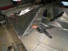
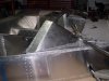
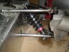
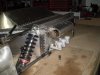
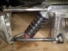
Hi Jack, 13.75" at the pedal face and 15.75"at the hip position in the seat area and the same on the passenger side. I'm 5' 8" and pretty solid Build and there won't be a lot of padding on the sides of the seat and you don't drive this in work boots if you get my drift. The other thing is there is only 10" height in the foot well, with my race shoes (size 9) I can operate the pedals but there is not a lot of spare room above my toes, also the steering rack goes through the same space about 6" back from the pedals (just above your ankel) so sliding in and out is an art.
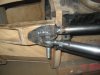
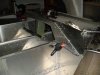
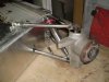
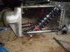
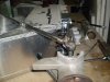
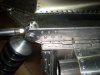
Hi Russ, you could be right?? I sort of copied the Tilton pedals so time will tell, as you may notice the brake pedal has not been painted as I still have to weld the balance bar in so I may take your advice and box the the front. thanks for the positive coments. I'm pretty happy with how its coming together so far and once the dash is done and the steering rack and suspension it should look pretty close to the original.
Cheers Leon