McCopy mk 5

Hi
Progress has been a bit slow lately, had to do some `home` work and add another guest parking spot. Been 18 years since I last did any earthworks...as the body will attest. The last computer cable arrived but plugged incorrectly so sent back for rewire, maybe 10 more days and then we can fire it up for the first time. All the engine wiring has been completed and now its onto the lights / fans etc wiring which all has to be on plugs as the body is removable.
Getting there.
Went to a tech night last week where the designer of the Beattie Clubman has a new project underway. Its a mid engine, 2 Ltr Alfa Romeo boxer powered car, also being road registered. Its also running the Willwood calipers. The workmanship and attention to detail is outstanding. The car is very light so should perform well.
 

Attachments

  • DSCN4847.JPG
    DSCN4847.JPG
    878.1 KB · Views: 442
  • DSCN4839.JPG
    DSCN4839.JPG
    341.1 KB · Views: 488
  • DSCN4840.JPG
    DSCN4840.JPG
    447.7 KB · Views: 481
  • DSCN4841.JPG
    DSCN4841.JPG
    378.4 KB · Views: 447
  • DSCN4842.JPG
    DSCN4842.JPG
    354.9 KB · Views: 510
More progress, made up the anti roll bar and all its parts today. Not much clearance but a miss is as good as it gets. All the oil cooler and filter set up also installed along with the dash. 99% of the wiring now done, just got to wire up the plugs for the headlights etc for when the nose gets taken off. Still waiting for my computer cable then its `start time`.
Gradually going thru the car and doing final fit checks so leaving no stone unturned.
Cheers
 

Attachments

  • DSCN4850.JPG
    DSCN4850.JPG
    445.7 KB · Views: 404
  • DSCN4852.JPG
    DSCN4852.JPG
    507.9 KB · Views: 405
  • DSCN4853.JPG
    DSCN4853.JPG
    518.1 KB · Views: 454
  • DSCN4855.JPG
    DSCN4855.JPG
    542.7 KB · Views: 482
  • DSCN4854.JPG
    DSCN4854.JPG
    525.4 KB · Views: 464
Looking good Russ, Question, what tube did you use for the roll bar set up?
cheers John
John, i used some very thick 19mm od chrome moly, it seems to do the trick.Not sure that with the car as wide and low as it is, that there will be any roll.
Cheers
 
Well last night was meant to be `startup`, thank goodness I did not invite the press!
After trying 6 different computors we went back to an old XP based one and finally it talked to the computor...(carbs are great). Then we spent considerable time confirming that it was wired correctly, (carbs are great). We could not get the TPS to co operate so more searching found that I had been supplied the wrong type of TPS. I had installed a switch type when it needed a variable one. After 4 hours (11.30pm) we then had to call it quits as it was not going to perform that night. After all this `crap` I was left feeling that 4 brand new 45mm Webber`s would have been a wise investment. They still say I won`t regret the choice once it runs. Anyway lots to learn is the story.
The rear spoiler got glued on yesterday and we are almost ready to do some serious sanding ready for the epoxy undercoat. I have been searching for weeks for a solution for my front park / blinkers and lucked apon an LED unit that fits perfectly in the lower section of my light boxes (slightly extended) For road going, the lights mus be no lower than 250mm, these will work out at around 255m so will need to pump the tyres up on test day. Pics to follow.
 

Attachments

  • DSCN4864.JPG
    DSCN4864.JPG
    574.5 KB · Views: 420
  • DSCN4865.JPG
    DSCN4865.JPG
    518.5 KB · Views: 397
  • DSCN4863.JPG
    DSCN4863.JPG
    462.9 KB · Views: 427
More little jobs today, when I cut in the light boxes for the headlights, I had forgotten about the indicators!!! After searching the world for suitable lights to `stick` on the outside, I found an LED light that was a perfect fit at the bottom of the light box ...if I extended them further down. So after a very careful measure, it was chop chop and then all done.
The indicator light will sit in the bottom of the light box leaving the flush look that I was after. For road registration, you can not have your lights any lower than 250mm from the ground. These lights will be 255 to 260mm above the ground. A pass is a pass. I think the longer deeper light box looks better anyway.
Still waiting for my TPS sensor to arrive.
 

Attachments

  • DSCN4868.JPG
    DSCN4868.JPG
    282.5 KB · Views: 419
  • DSCN4869.JPG
    DSCN4869.JPG
    396.5 KB · Views: 406
  • DSCN4859.JPG
    DSCN4859.JPG
    247 KB · Views: 406
  • DSCN4860.JPG
    DSCN4860.JPG
    170.9 KB · Views: 342
Spent the day with the LVVTC today getting serious over sorting out the road certification of the Mclaren and have a reasonable list to work thru. One thing that caught me out was that I was not allowed to use a GPS speedo! Its possible that my speedo head will accept other signals so was wondering if anyone could confirm the fitting on my 012 Audi trans,
I think the fitting close to the drive hub could be a speedo signal out put and the plug on the end of the cable could be the gear position signal. Any other suggestions would be welcome. The trans is brand new.
 

Attachments

  • DSCN4899.JPG
    DSCN4899.JPG
    514.2 KB · Views: 395
  • DSCN4900.JPG
    DSCN4900.JPG
    371.3 KB · Views: 298
  • DSCN4901.JPG
    DSCN4901.JPG
    261.2 KB · Views: 359
Hi Russel,
if the socket on the sensor is a 2 pin version, it should be a simple magnetic sensor .
take an ohm meter to see how much ohm it is.
on the otherhand to see if the sensors is functioning , take out of the gearbox and the far end should be magnetic .
if yes, when you move a metal in front the sensor at 3-4mm gap the readings on the ohm meter should varie.
if this is all like i suspect, then you having a magnetic speed sensor.
the other problem would be calibration between the number of pulses from the sensor side and the electronic speed gauge. solutions like this one exist
: http://www.atrol.com/era.htm.
Paul
 
forgot..... it could be possible that your receiver.... the speedoclok is polarised , and if not working while connected up to the sensor, you should change polarity of the wires on the sensor socket
Paul
 
Paul
Thanks for that, electronics is not my field but I can understand your comments and will check. The speedo head is VDO and I have found a good agent close by so once checked, will go and have a natter.
 
Paul
Thanks for that, electronics is not my field but I can understand your comments and will check. The speedo head is VDO and I have found a good agent close by so once checked, will go and have a natter.
I have just been and pulled the `sensor` out of the tranny and yes when I pass a magnet by it i get a signal so it looks like i can get something sorted.
 
Very fortunate that its not the local inorganic collection day, yesterday was spent with the low volume inspector and 31 points later plus a lump of cash I was not short of jobs to do. 90% were small things like one thread showing and 2 are required, lock washers missing despite locktite and rear brake line run up inside the central spine being a no no. They need to be visible for inspection and clipped every 300 mm. I also missed getting the brake pedal crack tested. No GPS speedo allowed and I have to some how prove that a stock standard steering shaft is `standard` and came from a Corolla (ex pick a part). I have already cleared 5 of the items so just have to get on with it..Thank goodness I have kept all my receipts so could prove what most parts were.
So last night we had start attempt no 3. 4 hours later we actually got it to start and run....very smokey as it was quite fouled. After all these attempts including new plugs and reco of the injectors which were in a sorry state we still could not get the timing right and we still suspect that the computor base map has a rotary map component that should not be there.....we find that the plug into the igniter box is not pinned as per the colour code install manual. I had followed the install map faithfully. We were getting multiple timing and 90deg out. My good long suffering friend Andrew got brave, cut / swapped wires and it finally fired and ran. We called it quit`s at 11.30 pm. Still work to be done.
 
The brake peddle must be made out of 8mm thick steel, no mention of how wide (chord) it should be, mine is made from one piece of flat bar and yes the pivot points are tig`ed and that needs crack testing. The Toyota Corolla steering universal`s with a factory welded short spline....I have to prove that I did not weld them and get a photo of one installed in a Corolla??? just going to get them crack tested all the same, less hassle I hope. There have been a few cases lately of dodgy inspections so everyone is covering their backside.
 

Terry Oxandale

Skinny Man
Russell, I've got a spoiler question. I'm finally going to build the spoiler for my project, and am working toward one that is close to the size of the original "A" spoiler. I can only go by drawings and other references that are not absolute, and mine will be slightly narrower (has to fit in a trailer, so I've reduced it by an inch on both ends), but the height should be close. Looking at photos of the original, I'm concerned that the fastening system used by the team is sufficient given the size of the original, and the drag produced at speed. Obviously this method must have been successful for the team, but it makes me wonder if there was some other support under the surface of the spoiler that was unseen by cameras. Yours appears to be a little shorter, and at a reduced angle (from horizontal), so not sure it is comparable, but in the few times you've had it at the track, have you had any issues with its attachment method? I'm only at the stage of creating templates for foam and/or aluminum in case I want to try this with alloy instead.

standard.jpg


standard.jpg


standard.jpg
 
Terry,
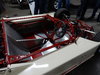
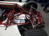
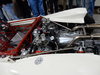
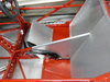
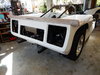
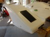
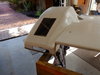
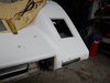
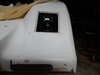
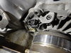
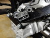
yes mine is purely `style` over function because I just like the look. The M8b car never ran these spoilers so we are both steeping outside the facts.(who cares) To make mine. I just waxed the body prior to paint prep and bondi`ed the shape onto the rear. I shaped it as much as possible before it popped off. This area of body is quite strong so when it came time to attach (after plenty of cleaning and prep) I simply pre drilled all the rivet holes using cleco`s to keep things aligned. Once I was happy, Called my trusty assistant Carol in and mixed a very sloppy bog, smeared in the right places and we went like hell, Carol putting rivets in the holes and me setting them before we had any cure. All achieved and cleaned up with a very strong connection achieved. The spoiler still looks the part under the high wing. I like the look of your body work, where did that originate from. Paint prep and final coat is planned in the next few weeks for us as I have been having all sorts of trouble getting this 1UZ started, turns out the one of the computer plugs was pinned incorrectly to the diagram..that took some finding.
 
Back
Top