Roaring Forties 105

it should fire next week.
We tried on Friday night but the Original Ford coils gave us grief so I will put on those that are tried and test.
Everything is go so bodywork soon I think.

Jim
 
Last edited:
Some shots of the exhaust finished
 

Attachments

  • DSCF0034.JPG
    DSCF0034.JPG
    49.5 KB · Views: 791
  • DSCF0033.JPG
    DSCF0033.JPG
    48.9 KB · Views: 778
Front wheels with flat of set.
I had the casting machined to give the optical illusion that there is more rim.
I will need to modify the spinners as I may carve up pedestrians.
 

Attachments

  • DSCF0038.JPG
    DSCF0038.JPG
    32.1 KB · Views: 719
  • DSCF0037.JPG
    DSCF0037.JPG
    40 KB · Views: 765
Wiper motor assembly.
It has adjustable sweep 2 speed and park.
 

Attachments

  • DSCF0004.JPG
    DSCF0004.JPG
    34.8 KB · Views: 608
  • DSCF0005.JPG
    DSCF0005.JPG
    37.6 KB · Views: 654
Hey Jim,
That is one sexy exhoust, I bet she'll sound as good as she looks! I always look forward to seeing what new creations Jim C has come up with. What is the oil cooler for? Engine or gearbox. I'm looking at making a cooler for the box in the near future.

Bob
 

Chuck

Supporter
Beautiful work. That wiper assembly looks beefy enough to handle not just a rain shower, but a major flood!
 
Bob
It will be quite as I have to get through the engineering (RTA).
That is my pryority.
The cooler is running exhaust gas to lower the NOX.

Chuck
Yes I dont think it will fall apart.
The rack and pinion I laser cut out of 316 10mm.
It works great better than I thought.
The problem is the sweep,you can not do it on a linkage as it goes over center,then the wiper arm runs across your front clip.
The rack allows you as much sweep as you want.

Jim
 
Last edited:
While I was doing the emission testing with the RTA, they never checked the noise levels of the exhoust, that was done by my engeneer. Thats a cool idea about cooling exhoust gasses to reduce the NOX levels. Good luck with everything and go to Penrith for testing as the operator is better.
Cheers
Bob
 
Jim, I take it from the above comment that you are running the exh gas thru the cooler on the way to the EGR valve, and you appear to source that from a small 'in pic' balance pipe just behind the collectors.
 
Thanks Bob

Jacmac
Yes that is correct.
Maybe you can shead more light.
I am still uncertain on the theory behind it.
EGR increases the combustion temp and reduces the NOX.
A conversation with my engineer he told me the cooler reduces the NOX.
The only puzzle I have is a turbo intercooler will increase the NOX due to lowered combustion temps, in theory that is what I am doing here so why does it work with the opposite reaction?.
Maybe it allows more volume because it is dencer or maybe you will require less EGR because it is dencer this allowing more room for a clean charge in turn making more torque and requiring less throttle and lowering the grams per KM readings in the test,I am shaw it will be a one armed juggling act getting the 5 gasses were they need to be.
I will be blocking air flow to the cooler when we go to the dyno to check the difference.
The EGR also is controled by my ECU so we will be writing a map to control the correct amount of flow at any given point.

Jim
 
Last edited:
The difference between a "build" and a really good "build" are the details. You are doing a fantastic job so far. Don't despair the myriad of minor details, although it takes some extra time. I went so far as to polish most of my aluminum mono and associated panels. Only took about an extra week. It is well worth the effort in the end. Keep up the good work!
 
I have not posted for some time so I will update.
I cant remember the order of some of the work so I will just put it up in what ever order.

Confession time

I had already built the front uprights but was not happy with my wheel offsets on the front and decided that I cant live with it.
The off set was due to reducing scrub radius, longer suspension arms and several other things that I decided that I was looking for.
Keeping in mind that I educated myself as I went along and was prepared for some learning curve, I don’t regret any of it other than I spent more than I had to.
A friend walked into my shop when I was rehashing this and he said “WHAT ANOTHER SET OF UPRIGHTS”
My reply was when I am finished I will be better at it than you.

The front wheel looked to flat.
With the 16” wheels I was also not happy with the lack of tyre in the arch.

I made a decision and an expensive one to redue the wheels but this time I would make them myself to have more control over the end result.

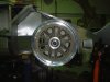
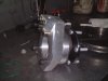
The main issue was trying to steal space from somewhere as I wanted to retain the arm length, this came from the disk offset.
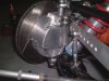
The original disks I used had an 83mm offset 300x 28 thick aprox.
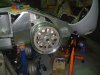
The disk I selected is 51mm offset 300 x 30 thick, this meant the Brembos had to go due to disk thickness and I can not fit them under a 15” rim.

The 32mm that I gained I moved the wheel flange in by 17mm and the disk further out by 15mm, as I was chasing a better ackerman angle and needed room for the steering arm.

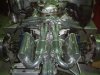
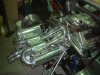
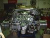
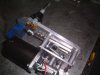
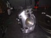
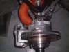
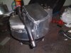
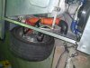
The upright is 6061 t6 I made it 20mm taller to use less spacer for roll centre adjustment, I incorporated the calliper mount , upper ball joint mount is removable and keyed into the main section of the upright so the bolts don’t take all the load under brakes.
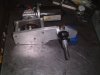
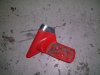
Steering arm is separate and is held by the 2 lower wheel bearing mounting bolts.
The assembly is 1 KG lighter than what I had, also A massive reduction in components.
I had 13 individual pieces to be welded on the original and 4 bolt on components on the new that is a win for me as it keeps it simple.
 

Attachments

  • DSCF0051-1.JPG
    DSCF0051-1.JPG
    32.1 KB · Views: 646
  • DSCF0052-1.JPG
    DSCF0052-1.JPG
    27.5 KB · Views: 594
  • DSCF0055-1.JPG
    DSCF0055-1.JPG
    32.5 KB · Views: 651
Last edited:
The arms where a bit of a mission to get them the same but once I worked out the technique I got them within a bees dick of each other.

I then made a new heat shields for brake ducting that encapsulated the upright and gives plenty of entry area.
The hose had to come in at the back to clear everything in bump and droop.
 

Attachments

  • DSCF0054-1.JPG
    DSCF0054-1.JPG
    38.5 KB · Views: 573
  • DSCF0061-1.JPG
    DSCF0061-1.JPG
    36.2 KB · Views: 557
  • DSCF0016.JPG
    DSCF0016.JPG
    43.5 KB · Views: 529
Last edited:
Made the windows, I spent a lot of time with a dummy window deciding what I wanted.
The car feels claustrophobic so I chose to make a pop out window.
It has toggles on the back that rotate 90deg , the outside of the pop out window has a brass frame around the outside with a seal on it.
It seems to work fine.
 

Attachments

  • DSCF0007.jpg
    DSCF0007.jpg
    39.8 KB · Views: 613
The mirrors I got of a 92 Toyota Celica.
I never had any intensions of using a corner mount mirror as I thought they looked to modern but when I found these I liked the shape , it has a swept look.
The top corner needed a sort out to make the shape fit the door.
I cut the and welded on a sheet section to take its place then used body filler.
They are electric and give really good visibility.
 

Attachments

  • DSCF0050.jpg
    DSCF0050.jpg
    38.7 KB · Views: 510
  • DSCF0006.jpg
    DSCF0006.jpg
    32.9 KB · Views: 538
  • DSCF0010.jpg
    DSCF0010.jpg
    40 KB · Views: 524
This vent I made to pick up from the naca duct, the seal closes down onto the hole with a shutter.
The shutter is cable operated and allows fresh air into the back of the blower fan.

Story time
I tried making the duct out of fiberglass (I dont know why) so I made a plug and for the next 5hrs I pissed myself off trying to get sticky s**t to work.

DUCT, BIN

Aluminum, 2hrs later ,formed welded fitted,

Lesson # 100,000001
 

Attachments

  • DSCF0017.JPG
    DSCF0017.JPG
    37.5 KB · Views: 584
  • DSCF0019.JPG
    DSCF0019.JPG
    36.6 KB · Views: 566
Last edited:
It dawned on me that you have no room left in this car and I will need to carry some tools and a jack or Tyre repair kit ect ect.
I dont want to use the door pockets because of the weight on the hinge adjustment with an open door so I used the space in the rear light boxes.

Made some boxes with flanges.
The covers then go over the top.

More story time
Fiberglass dosnt like me,I had all sorts of trouble pulling the box out of the mould because it is deep. it came out a mess because it was a bit green and looked like screwed up cardboard.
I patted it out and left it on the bench and Monday it looked brand new.
I think the F/Glass fairy came in over the week end.
 

Attachments

  • DSCF0021.JPG
    DSCF0021.JPG
    30.3 KB · Views: 531
  • DSCF0020.JPG
    DSCF0020.JPG
    35.9 KB · Views: 514
Last edited:
Back
Top