S2's Build Thread

I'm interested in how people torqued the steering arm to the top of the upright (see picture below). The two 3/8”-16 socket head cap screws (F1) are threaded into the steering arm (A) and then further held in place by the nylocs (F4).

IMG_1284.JPG

Scott - I don't seem to have an F3/F4 washer/nut on my upright assembly. It looks like you got too-long bolts. The bolts on my assembly are shorter and thread only into the tie rod attach point. I don't think you want to run the nut at all, go with a slightly shorter bolt.

qCNEz42.jpg


MfZGXjF.jpg
 
Scott has a much larger aftermarket brake package and a potential bigger duty cycle
Hence we run longer boots with loc nuts that are self locking against the upright in their application
 

Scott

Lifetime Supporter
I have the Brembo GT brake upgrade and everything about them is nice. The rotors, the anodization on the brackets, the castings, the powder coat finish, the documentation, etc. The bolts that attach the rear calipers to their brackets (right in picture below) were nicely finished and had a shank. The equivalent screws for the front (left in picture below) looked like they came from the bottom of the bargain box at a surplus store. The threads were rough, the finish poor and beat up and there was no shank. They stripped all of the anodization off of the bracket's threads (the rear bracket's anodization looked like new).
1488256260898


WTF? Surely someone at Superlite used the wrong bolts... Nope that's the way the fronts come from Brembo and 99+% of their brakes use them. That said, I wasn't crazy that there was no way lock them (Brembo is clear that no thread locker should be used). What to do? Upgrade to studs!
1488257098502

The Brembo studs are beautifully machined and have a really nice finish. Jet nuts and washers are used to lock things in place. According to Brembo tech support the studs should be installed finger tight with permanent thread locker and then the jet nuts torqued to 35 ft. lbs. to set the stud.

The following parts can be ordered from Race Technologies.

905577 Brembo Stud, Caliper Mounting, M12x1.50 Base Thread, 7/16"-24 Top Thread, 84mm Overall
WS-7 Brembo Washer, 7/16", Cadmium Plated
MS-7 Brembo Flanged Lock Nut, 7/16"-20, Cadmium Plated
 

Scott

Lifetime Supporter
I designed a 3D printed a part for a friend who's working on a skunk works project. If I told you what it's for, I'd have to kill you. It's designed to attach to the hexagonal rod on a linear actuator.
1488423358103

I printed it in Onyx which is composed of tough nylon and chopped carbon fiber. Since the part will see a fair amount of stress, I reinforced it with continuous strands of carbon fiber. The slicer provides two layout algorithms:
eiger_isotropic_fill.png

eiger_concentirc_fill.png

  • isometric: follow the outer edge a specified number of times (i.e., rings)
  • isotropic: diagonal fill

The choice between the two comes down to how you want to orient the strands for strength and how much continuous fiber (e.g., fiberglass, HT/HS fiberglass, Kevlar or carbon fiber) you want to use. Isometric allows you to control how much continuous fiber is used by specifying the number of rings whereas isotropic fills the entire layer. The proprietary carbon fiber is expensive, so you want to be conscious of how much you use.

For this part I used isometric layout to provide strength where it's needed and to reduce the amount of continuous fiber. In a previous post I had pointed out that their isometric fiber routing algorithm didn't wrap interior holes unless there were enough rings to intersect the hole. For example, in the image below three are three rings around the perimeter, but none around the hole. Even then the rings intersect the hole, they weren't optimized to reinforce the hole.
1488419873427

I was concerned about this shortcoming because the all of the stress will be transmitted through three interior holes -- yes, they have press-fitted metal bushings, but that's where we want the most reinforcement.

When I went to print the part I was thrilled to discover a new "Walls to Reinforce" setting with the following choices: All Walls, Outer Shell Only, Inner Holes Only. One of the advantages to having a cloud-based slicer is that upgrades are automatic. In any event, for this print I selected All Walls and two rings. This wrapped the outer shell and the three inner holes with two rings of continuous carbon fiber. Note how thick the outer shell and inner hole walls are. Also note the hex recess. The material inside the notch on the left (i.e., the hex recess) is to support the horizontal ceiling of the hex which hasn't been printed yet. If you look carefully you will note that this support material doesn't span the entire opening because the faces of the hex that support the ceiling don't need support material. In other words, Onyx can be printed with a 60-degree overhang.
1488422727878

While we haven't done any destructive testing yet, the part feels very robust and nothing like nylon.
Srut1.jpg

Strut2.jpg
 

Scott

Lifetime Supporter
I think I might have the first hybrid (gas/electric) with this mod LOL

I know that there has been some debate whether or not a fan shroud is a good idea or not and if upgraded fans are necessary. I wanted to do everything possible to ensure that I wouldn't have an issue. I spoke with Chuck at Superior Radiator who manufactures the SL-Cs radiator and he suggested a shroud and upgraded fans, all of which I bought from him. The shroud is made of 0.65" aluminum and the fans are much larger than the ones that came with the kit (in the two pictures below, the new fan is on the left).
IMG_1356.JPG


IMG_1355.JPG


The old fans are rated at 1,300 CFM (I think) whereas the new ones are rated at 2,000 CFM. Chuck indicated that they are more of a wholesale item with a minimum purchase of 100 units so I don't have a part number.

He didn't think that I'd need flaps, but I decided to add two just to be safe. I wasn't sure what to make them out of so I ordered two from Summit Racing. They were replacement parts and as such had no specifications. The SPAL Automotive ($1.31) and Be Cool ($6.99) flaps were indecipherable. Fortunately, at 3.3" x 2" they were a perfect fit. There is nothing special about them. They're made out of floppy 0.4" rubber and have three molded mounting spikes which I cut off. So, it's trivial to make your own.
1488680969918


Here are the flaps installed. I cut off the three mounting spikes and used screws and nylocs.
IMG_1364.JPG


I will have temperature sensors on both the cooling and AC pipes and I'm in the process of figuring out how to control the fans with the MoTeC ECU and Power Distribution Modules (PDMs). Each fan draws 17 amps when running and 23 amps when starting up. This gives me two options:
  1. Use a single 8-amp output to drive an external relay
  2. Use a 20-amp output for each fan
The advantage to the first option is that it only uses one small output. On the downside, it requires a relay (more wiring and a potential failure point) and results in a bang-bang control loop (i.e., either all on or all off). Fortunately, the MoTeC configuration software enables you to configure both a temperature-based threshold and hysteresis (see image).
1488681814618


The downside of the second option is that is consumes two large outputs. However it has significant benefits; it requires no external parts and the fans can be individually controlled via PWM. In addition, the 20 amp circuit can handle startup spikes up to 115 amp as well as a "digital" fuse which can be configured in one-amp increments with multiple auto-reset options. While bang-bang circuits work fine in most cars, 2,000 CFM is a pretty big bang and PWM provides fine-grained control via software which means that the big fans shouldn't be a liability... the only get maxed when it's warranted.

I'm happy with the shroud, but if I had it to do over again I would ask Chuck to not mount the fans (no need to drill them out), cut the flap holes (less work) and make the shroud a little deeper (just to be on the safe side).

I'm happy with the shroud, but if I had it to do over again I would ask Chuck to not rivet the fans (I just drilled them out), cut the flap holes (less work) and make the shroud a little deeper (just to be on the safe side). You can buy the shroud and fans from him for $350. My guess is that he'd also make a shroud for the fans supplied in the kit.
 

Scott

Lifetime Supporter
I have a few questions regarding the rear hub and stub axle:

(1)One of the stub axles is drilled for a cotter pin and the other isn’t. They have slightly different nuts on them so they might have come from different suppliers. Does anyone else have a stub axle that isn’t drilled? I’m thinking that since it’s made out of some hard-ass steel I should bring to a machine shop to have drilled.

(2)In looking at pictures/diagrams of C4 hubs, many seem to have wheel bearing nuts. The nuts have a thin shoulder on them which looks like it's designed for the wheel bearing nuts, so I assume that I should order two of these: (1984-1996 Corvette Rear Axle Shaft / Wheel Bearing Nut).

(3) I know that these are high-quality parts that Superlite has made for them in the USA so I assume that there isn't a manual from the supplier. The '86 Corvette manual states 164 ft lbs. Apparently, this was subsequently revised to 183-192 ft lbs in a GM Service bulletin. Others claim 200 ft lbs. Left to my own, I'm going for 185. What are you guys torqueing yours to?
 

Scott

Lifetime Supporter
Mesa,

I'm not sure what happened to my last post... it seems to have been deleted (I pasted it below). I have no idea why they call it a "nut" in that page -- I assume it's a typo. If you look here they call it a retainer. It's a thin piece of metal that sits on top of the nut and apparently engages the cotter pin somehow. The nuts that came with the axle have a tall, thin shoulder that should prevent the nut from loosening past the cotter pin. That might obviate the need for the retainer, but without a parts diagram I'm just guessing.


DELETED POST
-----------------
I have a few questions regarding the rear hub and stub axle:

(1)One of the stub axles is drilled for a cotter pin and the other isn’t. They have slightly different nuts on them so they might have come from different suppliers. Does anyone else have a stub axle that isn’t drilled? I’m thinking that since it’s made out of some hard-ass steel I should bring to a machine shop to have drilled.

(2)In looking at pictures/diagrams of C4 hubs, many seem to have wheel bearing nuts. I assume that I should order two of these: (1984-1996 Corvette Rear Axle Shaft / Wheel Bearing Nut) .

(3) I know that these are high-quality parts that Superlite has made for them in the USA so I assume that there isn't a manual from the supplier. The '86 Corvette manual states 164 ft lbs. Apparently, this was subsequently revised to 183-192 ft lbs in a GM Service bulletin. Others claim 200 ft lbs. Left to my own, I'm going for 185. What are you guys torqueing yours to?
 

Scott

Lifetime Supporter
Unit and functional testing is critical to software development, but it also extremely useful when printing 3D parts. It can significantly reduce the cycle time and material to develop a part. More importantly, it can result in a high-quality, well designed part.

In computer programming, unit testing is a software testing method by which individual units of source code... are tested to determine whether they are fit for use. Intuitively, one can view a unit as the smallest testable part of an application.

— Wikipedia

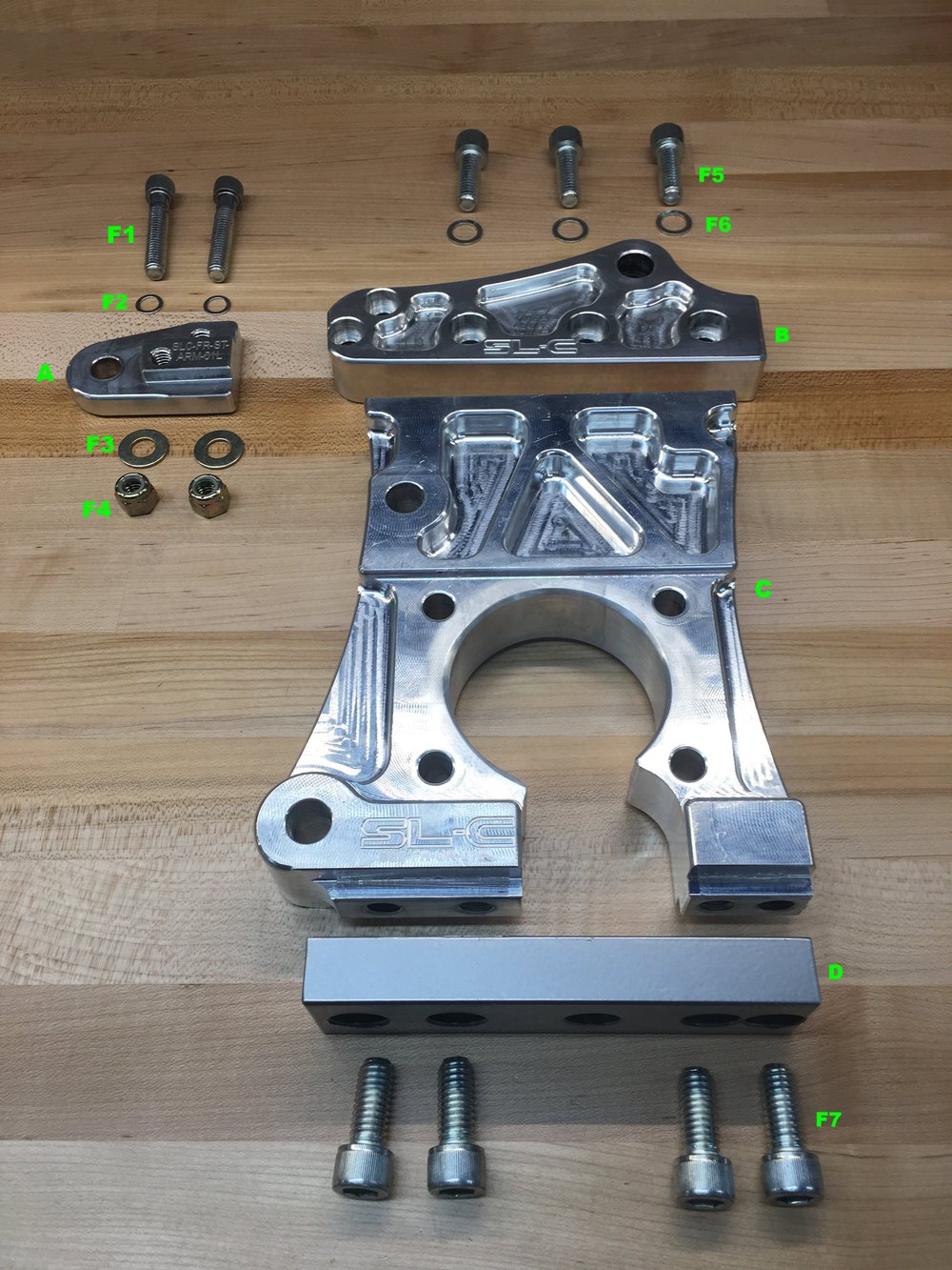
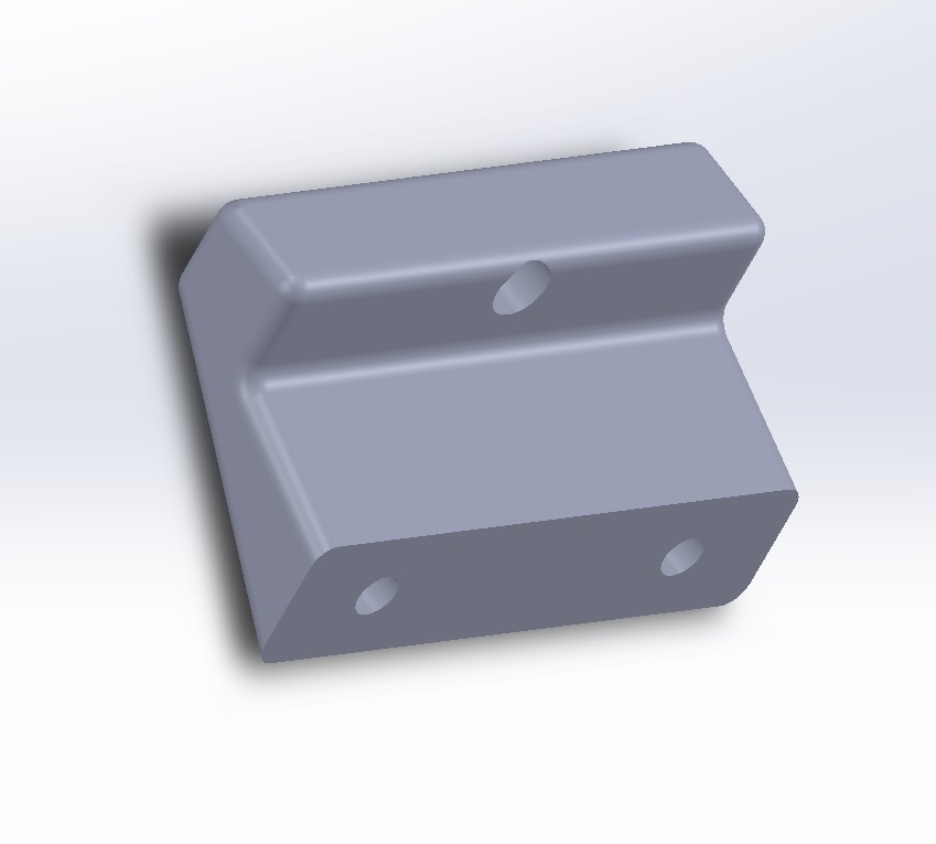
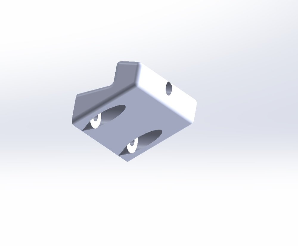
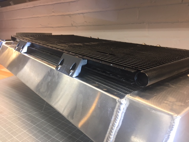
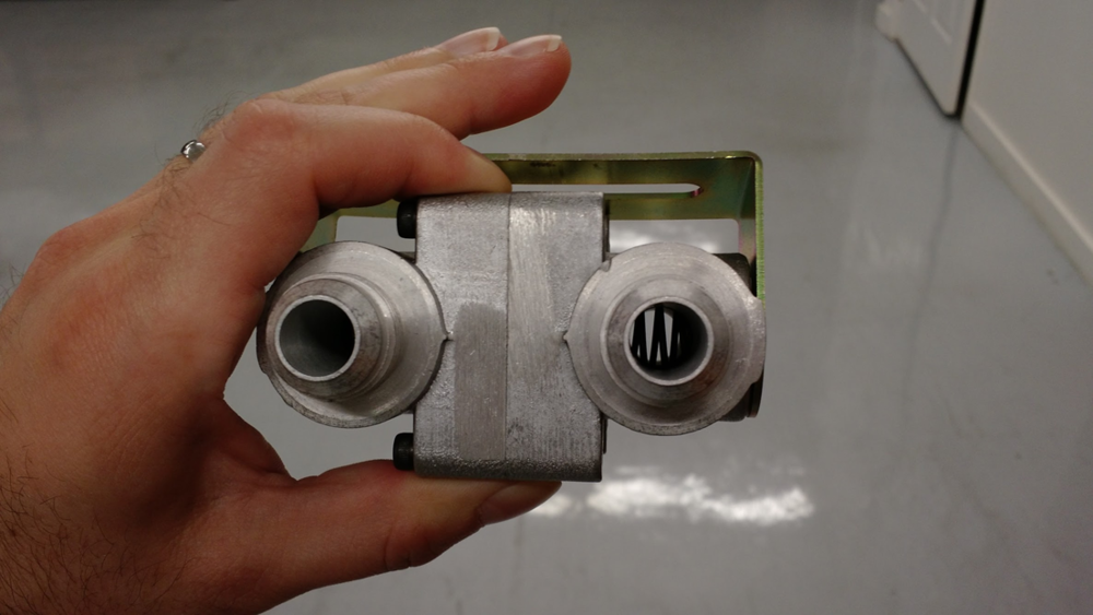
When creating "unit tests" for a 3D-printed part, you want to print the smallest piece possible to validate the critical dimensions that you're worried about. For example, I recently designed a bracket (see pictures below) that mounts the bottom of the condenser to the bottom of the radiator. While not a complex part, there were several critical dimensions that I knew would take me a couple of iterations to get right. Rather than printing a full size prototype, I broke it down into "unit tests." Once the part is designed, you can usually use one or two extruded cuts to slice the completed part into something that you can use to unit test. SolidWorks allows you to suppress these cuts and save them in part file... yeah, just like software you sometimes make a change that breaks something else and the more complicated the part, the more likely it is to happen!
LowerCondendorv2_1.jpg

LowerCondendorv2_2.jpg

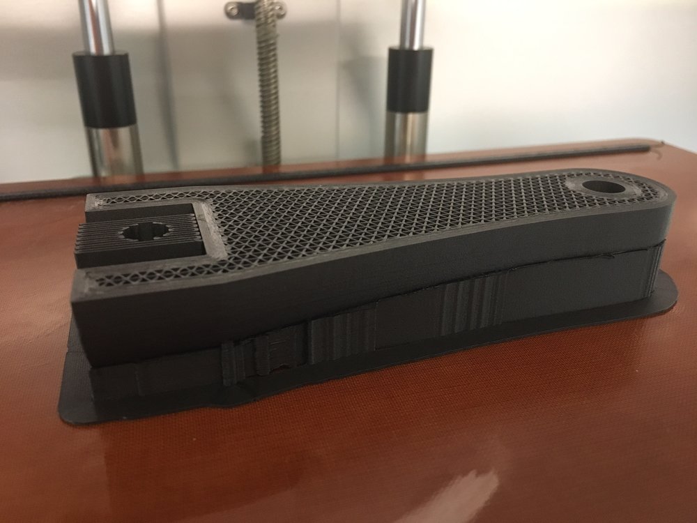
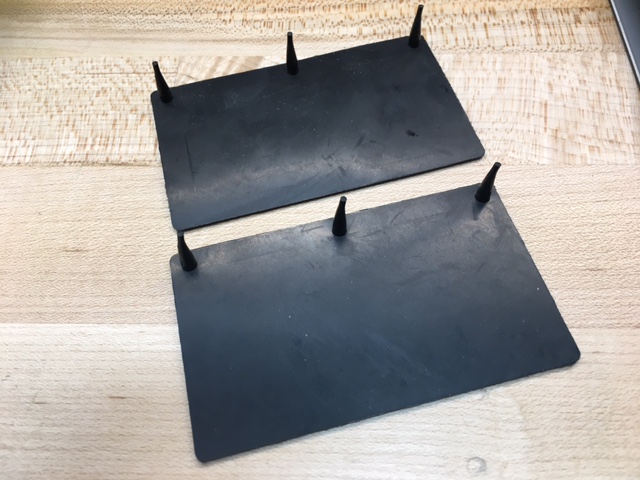
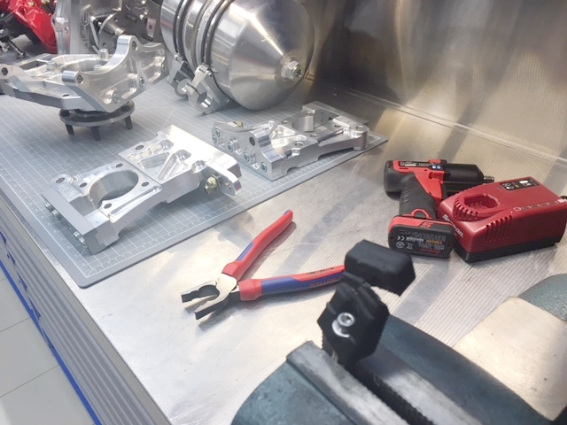
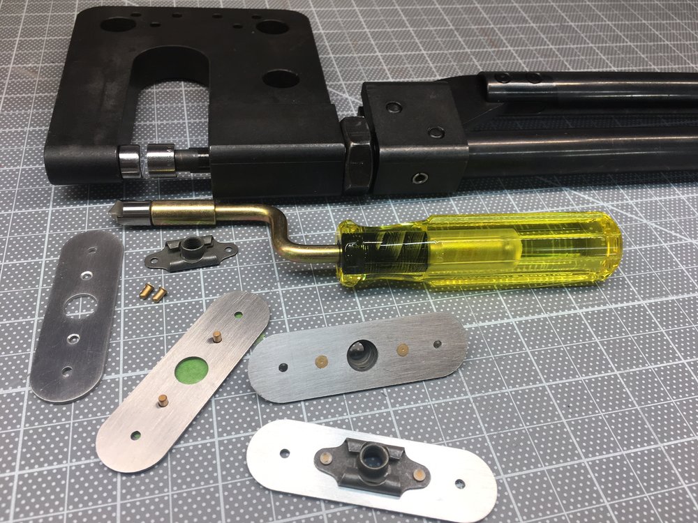
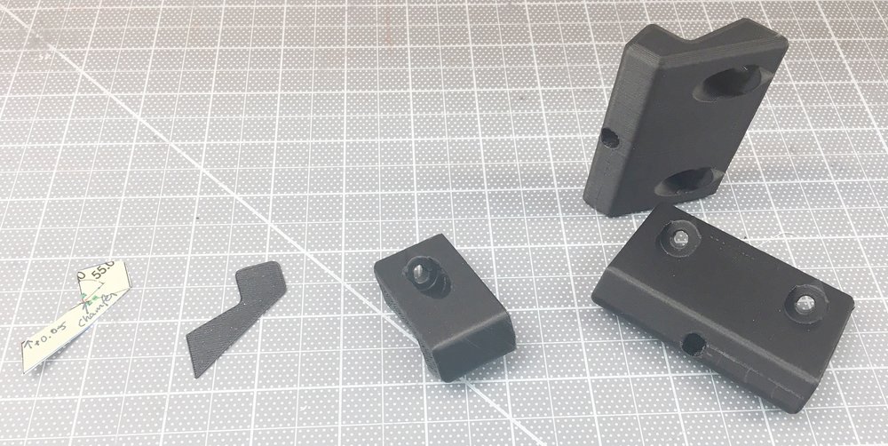
The picture below shows the four steps to get to the final production parts. From left to right:

  1. The profile of the part was printed on paper in 1:1 scale, cut out and trial fit. I needed to extend the part that touches the radiator by 0.05" and I noticed that I had room for a internal fillet.
  2. I made the changes and then printed a 0.025" slice in Onyx. Oops, that 0.05" should have been more like 0.04".
  3. After making that change I printed a section to test: (1) the part that fits into the bottom of the radiator and (2) the hole that is recessed into the sloped face. Typically I would have split this into two tests, but I already had designed a bracket for the top of the radiator so I was pretty sure I would get the right. Number one was perfect and when snapped into place it was held there by friction (I think that took me two or three times to get right when doing the top bracket). Number 2 wasn't so successful. I was able to get a washer to sit flush in the recess after using a utility to carve the sides a bit so I increased the diametera bit.
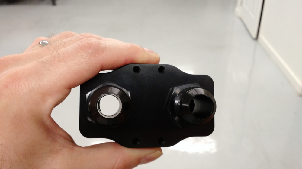
  4. Final print.
1489623745669

The value of the unit tests becomes apparent when you look at the amount of material and time for each iteration. The savings become even more dramatic for a larger or more complex part. I got to an optimal part (at least in my mind LOL) in a small number of iterations. Having a 3D printer in the garage made that a fast and easy process. If I had to send the part out to be printed the elapsed time would have been much longer and the part not as good. Less iterations means less chances to tune the part and you're likely to say "good enough" much sooner than you would with a short cycle time. My recommendation is that if you're going to design a bunch of 3D parts to at least get an inexpensive printer so that you can quickly iterate designs and then have the final part printed by someone else with a high-end printer.

Iteration......... Material........... Print Time (Minutes)
1............. 1 Sheet Paper.............. 0.1
2............. 0.21 cm³ Onyx............ 5.0
3............. 4.14 cm³ Onyx.......... 34.0
4............ 25.02 cm³ Onyx.........153.0

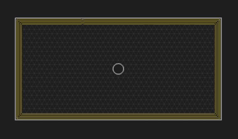
The unit tests were printed with the settings to to reduce time and material. The table below shows the settings that I used for the unit test vs. the system defaults:

SETTING................UNIT TEST..........DEFAULT

Fill Density (%).......... 1.......................50
Wall Layers................ 1.......................2
Roof & Floor Layers..... 1.......................2
Layer Height (mm)....0.2....................0.1

The unit test parts can also be useful for destructive testing. If it's strong enough when printed at unit test settings, then it's going to be more than strong enough in the final print. In addition the final part was ~2.5x wider and has an additional screw, which provides a lot of margin.

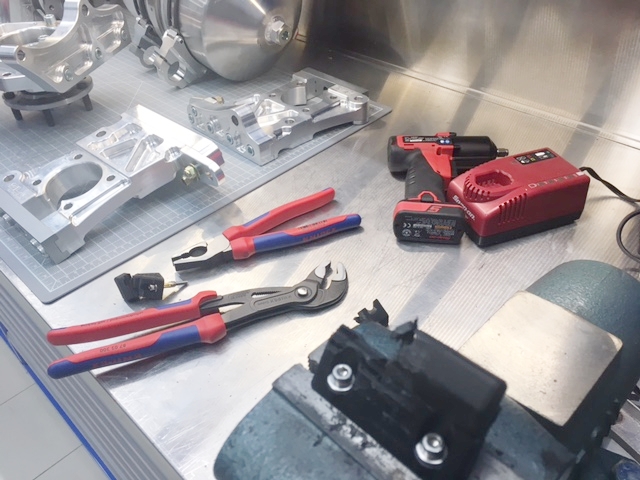
Well that didn't work for this part. It was pretty easy to break the one-inch wide, crappy print. After going to install the final part I decided that the part overhung the bottom of the radiator by 0.06". It doesn't affect anything except my OCD. So I decided to destruction test that one. I had to get a bigger set of pliers to break it and it broke where you'd expect it to break. It's strong enough as is and don't I think that I'm going to use any continuous strands in the final-final print. That said, given the print orientation the continuous strands would be optimally oriented and I could make that axis as strong as a solid aluminum piece.

...yeah, like software you can keep just tweaking it...

Unit Test Piece - Destroyed
IMG_1397.JPG


Final Piece - Destroyed
IMG_1399.JPG
 

Scott

Lifetime Supporter
Well, the "unit tests" that I wrote about in the last post only took me so far. When I went to mount the brackets I realized that I hadn't made recesses to accommodate the lips on the rivnuts (I didn't install them until after I printed the parts). Any easy fix, but it forced a reprint. In any event, I'm pleased with how the brackets came out.
1489779277295
 

Scott

Lifetime Supporter
My son doesn't have school this week and we decided to drop by the Lars Anderson Auto Museum. It's about a half mile from our house and it houses "America's oldest car collection." He hadn't seen the new Porsche and BMW display which features a Porsche speedsters, 959s, 930 turbo and 956, plus a BMW M1. The 956 was my son's favorite car.
IMG_1425.JPG

IMG_1426.JPG

IMG_1427.JPG

IMG_1428.JPG

IMG_1430.JPG

IMG_1439.JPG

IMG_1440.JPG

If you're in Boston, it's worth a visit. It was built in 1888 as a stable, but began to house horseless carriages starting with the purchase of an 1899 Winton Runabout. When Isabel Anderson passed away in 1948 she bequeathed her entire Brookline estate, including the mansion, Carriage House and land to the Town of Brookline. Fourteen of their cars remain, including two electric cars built in the 1920s.

I got the the picture with grass off of the web... there's still snow on the ground in Boston! That's the carriage house, the mansion burned down years ago.
1490233839237
 

Scott

Lifetime Supporter
I have the removable side-impact bars which take up room in the foot box such that the Vintage Air evaporator doesn’t fit. I know that several builders have used the Hurricane evaporator made by Old Air Products. I was hoping someone could provide some feedback on the Hurricane or any other evaporator they’ve used in a SL-C.
 

Scott

Lifetime Supporter
Allan, thanks for the pointer. Bob has a really nice build. I'm curious how he ran his heater lines inside the foot box.

I started to work on the heating and a/c systems. First step was to make sure I knew how everything is connected.
CoolingSystem.png


I used this heater control valve (HCV) which was recommended by pnut. The business end has four 5/8" hose barbs and a valve. Connected to the valve is a servo which is wired to a separate servo controller which is in turn wired to a potentiometer. This provides continuous adjustment from closed to fully open. There are five wires (two for power and three for the position feedback potentiometer) so it's a closed loop control system.

I considered controlling the HCV via MoTeC by replacing the potentiometer with a digital potentiometer controlled by an Arduino which would then be interfaced to the MoTeC. It would work, but it's a fair amount of work, introduces a bunch of things that might break and I don't really gain anything... nah, not worth doing.

The HCV is awkwardly shaped and there is no easy way to mount it. While pondering the best way to mount it I noticed that the actuator fit perfectly in a triangular dead space in the 2" x 6" chassis. I then realized that I could remove the three screws and and spacers connecting the actuator to the valve and sandwich an aluminum bracket and replace the spacers with shorter ones... OR I could just print a panel large enough to seal the hole (something that was on my to do list) and mount both the motor controller and wire connector.
IMG_1469.JPG

IMG_1467.JPG

The panel is sandwiched between the valve and actuator, thus replacing the standoffs. It was made large enough to cover the hole and mount the motor controller and a new wire connector. There wasn't a way to mount the motor controller so I simply drilled the cover plate mounting holes all of the way through and used stainless 4-40 screws and nylocs. Since heat rises, I decided to print a heat shield between the heater lines and the motor controller and to put Reflect-a-GOLD on it. I cut 80% of the harness off and terminated one end into a Deutsch connector. I removed the connector to the actuator, fed the wire through a vinyl grommet and re-terminated it on the back side. Since I couldn't figure out what type crimp connectors were used I carefully cut the old ones out of the harness and soldered them on. It's all in one tidy package now...
HeaterControlValvePlate.png


IMG_1470.JPG


IMG_1472.JPG


IMG_1473.JPG
 

Scott

Lifetime Supporter
Thanks guys, it was a lot of fun making the part... and I got it right on the first print LOL

I received a new toy today from Injector Dynamics. You gotta love a company who puts the following on their home page and then walks the walk with innovative products back by data:
1492122716315

As a results based engineering company, we have a STRICT no BS policy. Our product information is backed by data, and sound engineering principles. Our strict adherence to facts has earned the respect of many, but our willingness to call BS when we see it has created a great deal of controversy. We accept this controversy as a small price to pay for holding the industry to a higher standard, and we will continue to push for a motorsport community that makes decisions based on facts, not buzzwords, nonsense, or outright falsehoods.

I saw this video made by the company's founder over a year ago and have been hounding them since. They don't have it on their site for sale yet, but I just got mine in the mail today...

Video link of founder discussing the fuel filter: A New Generation of Fuel Filter from Injector Dynamics - YouTube

Note that "April" was for 2016... they didn't want to release it until the had it right which is fine by me.

It came very well packed in a large box packed with the starch-based peanuts so they score well with environmentalists as well as my kids who love to dissolve them in the sink. I'll only outline what's in the video and this spec sheet:

  • Only filter I've see with actual testing data
  • Meets Bosch's specification for the protection of fuel injectors
  • Holds a high-level of contaminants while maintaing low restriction to flow
  • Delta pressure gauge indicates how clogged the the element is
  • Schrader valve to relieve pressure and drain gas
  • Spin on/off canister with no-tool safety latch
  • Optional pressure and temp block and sensor
  • Integrated mounting bracket
IMG_1479.JPG

IMG_1480.JPG
 

Scott

Lifetime Supporter
3e0.jpg

When I removed the center body from the chassis it took a little while to undo the five screws/nylocs on each side that attach them. The reason for this is that the bolts are mounted from the bottom of the car and you need to get a wrench on the nuts in the interior to keep them from spinning. I don't have long arms (no, they aren't T-Rex arms) and I needed another person to remove several of the screws.

In any event, I'm in the process of filling up the side pods with cooling, heating and A/C lines which will make installing and removing these screws much more difficult in the future. I considered using a long piece of aluminum and tapping five holes into it. The primary issue with that approach is that each side would need a piece nearly four feet long which costs money and adds weight. Worst yet, there wouldn't be anything to prevent the screws from shaking lose.

To solve this problem I decided to take a page from aircraft construction and use self-locking, floating nut plates. A nut plate provides a way to add a captive nut behind a panel. In addition, the self-locking type have an asymmetrical thread which deforms and locks the screw into place. Unlike jet nuts these nuts can be reused several times, but should be replaced when there isn't resistance when tightening. The floating version allows the nut to move forward/backwards and left/right which allows some misalignment during assembly, which is very useful when mounting the body to the chassis.
1492469643438

Since the nut plate needs to be fastened on the fiberglass side I was concerned with how close the rivet holes were to the fastener's hole. To resolve this, I had a bunch of mounting plates water jetted out of 1/16" aluminum. This was essentially "free" because I had them cut when the fan shroud was cut and they fit within what would have otherwise been scrap. I wanted the plate to sit flat on the fiberglass, so I used NAS1097AD3 rivets. They are 3/32" solid rivets that allow flush installation even in thin materials. The reduced head makes them inappropriate for when used in a structural shear application, but we're just using them to keep the nut plates from spinning.

In the picture below:

  • Solid rivet manual squeezer
  • 100-degree counter sink
  • Mounting plate with the inner two rivet holes countersunk (doesn't take much)
  • Two 3/32" solid rivets (NAS1097AD3)
  • 6-32 floating, self-locking nut plate
  • Rivets held in place with painter's tape (made riveting much easier)
  • Bottom of mounting plate post riveting (note that the rivets are perfectly flush)
  • Nut plate riveted to mounting plate
1492469602953

I haven't figured out what types of rivets to use to attach the mounting plates to the fiberglass, but it will be a long time before I need to sort that out.
 
Last edited:

Scott

Lifetime Supporter
I was about to purchase a Improved Racing FSM-165 for my transaxle thermostat when I realized that while it can be ordered with -12 AN male fittings, the female ports are just -10 AN.

@&#%! This is a problem because the manufacturer of the oil dry sump, Daily Engineering, is very specific that the pressure line (i.e., connection between the pump and the thermostat) must be -12. So, I spent a lot of time looking for a thermostat with -12 capacity all of the way through and only found one which I didn't like nearly as much as Improved Racing's.

I contacted Improved Racing and they had good news. The ID of a standard -12 AN straight hose end is 0.58" and their male fittings have an internal ID or 0.60". In addition, Improved Racing's thermostat is much less restrictive than other brands. The pictures below compares their thermostat to Mocal's, note how open their's is.

In any event, the point is that even though the FSM-165 has -10 female ports it will be the least restrictive part of the -12 pressure line.

ImprovedRacing_02.png

Improved Racing, no fittings

ImprovedRacing_05.png

Improved Racing, with fittings

ImprovedRacing_03.png

Mocal, with fittings

ImprovedRacing_04.png

Mocal, with fittings
 
This thread is fantastic S2.

I do have a suggestion with your unit testing 3d printing process. The markforged printer is great, but it is terribly slow! I have an entire lab full of 3d printers and it is by far the slowest printer of all of them. When designing for fit, you don't need to print unit tests in the final material which can be expensive $$$. You could buy an ultimaker or any other bowden type printer and knock out test prints in more than double the speed in an extremely cheap material like PLA.

I have a markforged mark 2 and I love it, but only print vetted designs on it, since it is soooo slow for prototyping.

BTW are you sharing any of your CAD and or STL files for your SLC build? I thought I was going to pioneer a build with custom onyx bits and bobs but you have beaten me to it!

Keep up the good work Scott!
 
Back
Top