
- Forums
- GT40 Replica Manufacturers' Corner
- RCR Forum - RCR40/SLC/917/Superlite Aero
- The SLC Clubhouse
You are using an out of date browser. It may not display this or other websites correctly.
You should upgrade or use an alternative browser.
You should upgrade or use an alternative browser.
S2's Build Thread
- Thread starter sswartz
- Start date
Scott
Lifetime Supporter
To clarify my prior question... all of the pictures that I've looked at show the throttle body mounted so that the actuator is parallel to the ground. I'm wondering if I can rotate the throttle body to any position that I want. For example, pointed up at a 45-degree angle as shown in the picture below.
Attachments
Scott the only concern is when the business end of the throttle shaft is pointed down. Reversion in the intake will ultimately draw fuel vapor back to the throttle plate. If the throttle actuator is pointed down the chance of gravity assisting these vapors and contaminants in migrating through the shaft seal into the electronics is high. The way you have it displayed in your image should not be an issue.
Scott
Lifetime Supporter
Chris, thanks for the information...
I 3D printed my first tool when installing the reluctor rings on the CV joints.
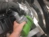
The first step was to remove the end caps which are held in place with a slight press fit and RTV (Room-Temperature-Vulcanization) silicone. It's my understanding that the silicone is used to prevent the grease from leaking out of the bolt holes. The end caps are made of thin metal, so I carefully tapped around the edge of the cap with a hammer and large, flat screwdriver. The first one took a while. The second one went much faster because I used a much larger hammer and bigger wacks ;-)
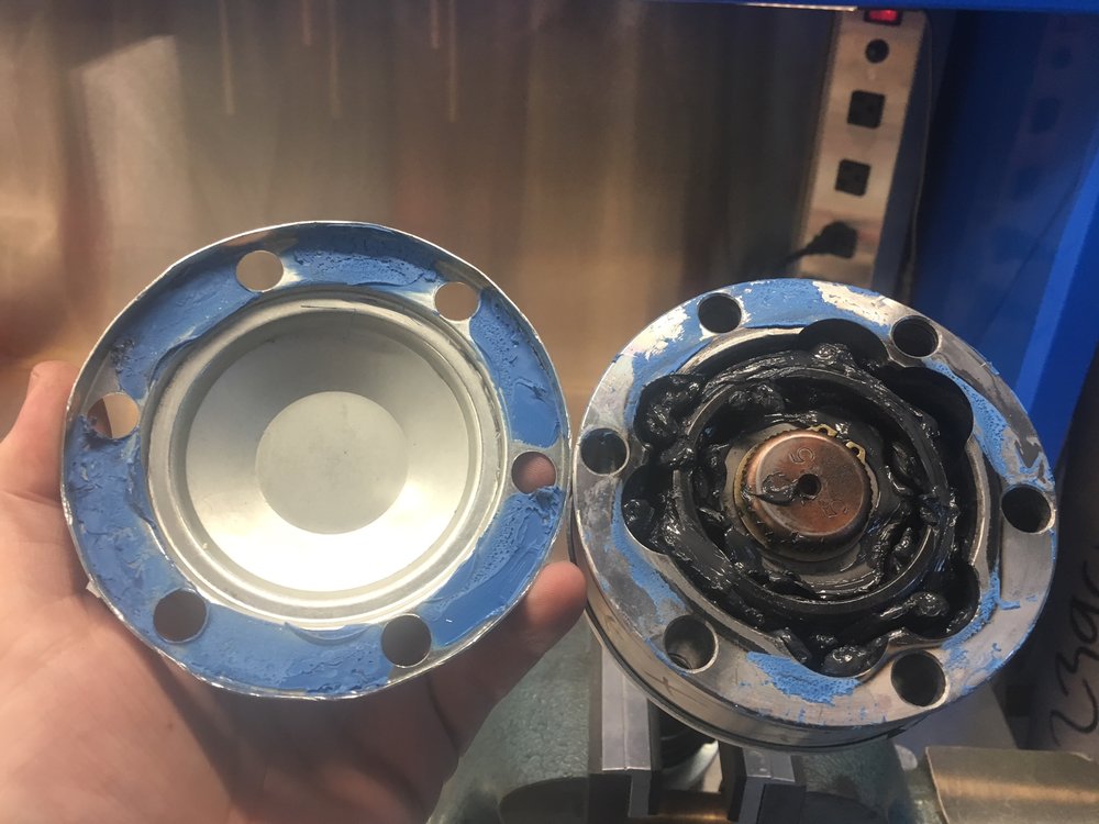
I then scrapped the silicone from the cap and the CV joint with a razor blade taking care not to let any pieces get into the grease. I was able to get almost all of the silicone off the the CV joint and then I used acetone and a metal finishing pad to get the remainder off. The cap was a different story. Apparently RTV silicone is pretty much impervious to acetone and most other solvents. After doing a little research, I bought some Permatex 80652 RTV Silicone Dissolver. It does soften thin layers of silicone, but it's a nightmare to work with because it has a jello-like consistency. It's almost impossible to get it to adhere where you want requiring you to use ten times more than you would think necessary... it was infuriating to use and I now fully understand some of the negative reviews on Amazon. That said, it was better than not having it.
The next challenge was to mount the reluctors on the CVs. They use a friction fit and no matter what I tried I couldn't get them on. I could get one edge started, but the reluctor would be crooked and the only way to fix that was to remove it. The answer was to design and 3D print some tools. Specifically, six locating dowels (three short and three tall) and a ring driver to apply even pressure on the reluctor when hammered. The only difference between the tall and short dowels is their height. Both hold the reluctor in place and ensure that it's concentric to the CV joint. The tall dowels also help hold the ring driver in place, but they restrict where you can hit the ring driver (a taller ring driver would solve that, but would require more material). The short dowels don't cause any interference and they require much less material to print.
Ring driver, three short and three tall locating pins
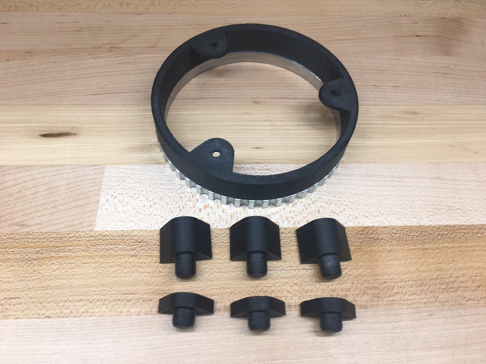
Six locating dowels
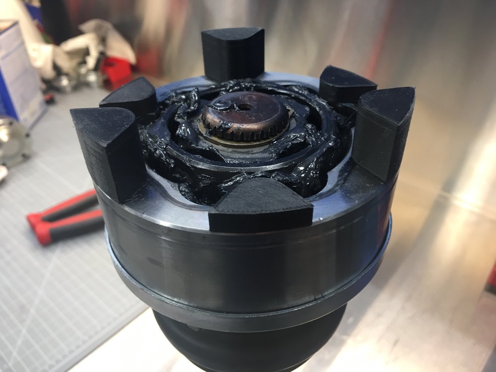
Ready for the ring driver
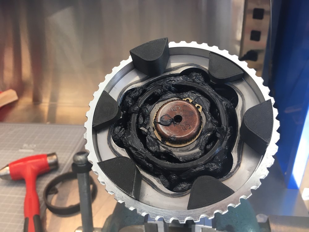
Reluctor ring installed

The process worked as follows:
The next step was to reinstall the caps. I used a hammer to carefully straighten the edge of the cap which had been somewhat misshaped when banging it off with the screwdriver. Once that was done, I applied Loctite 37461 Blue RTV Silicone Gasket Maker to the CV joints and gently tapped the caps on with a hammer. I immediately installed the axles so that silicone would be properly compressed before it dried. A little oozed out. I decided to mount the reluctor next to the transaxle rather than the hub because the hub bounces up and down. I may need to change this when I route the exhaust, but that's easy to do later.
I 3D printed my first tool when installing the reluctor rings on the CV joints.
The first step was to remove the end caps which are held in place with a slight press fit and RTV (Room-Temperature-Vulcanization) silicone. It's my understanding that the silicone is used to prevent the grease from leaking out of the bolt holes. The end caps are made of thin metal, so I carefully tapped around the edge of the cap with a hammer and large, flat screwdriver. The first one took a while. The second one went much faster because I used a much larger hammer and bigger wacks ;-)
I then scrapped the silicone from the cap and the CV joint with a razor blade taking care not to let any pieces get into the grease. I was able to get almost all of the silicone off the the CV joint and then I used acetone and a metal finishing pad to get the remainder off. The cap was a different story. Apparently RTV silicone is pretty much impervious to acetone and most other solvents. After doing a little research, I bought some Permatex 80652 RTV Silicone Dissolver. It does soften thin layers of silicone, but it's a nightmare to work with because it has a jello-like consistency. It's almost impossible to get it to adhere where you want requiring you to use ten times more than you would think necessary... it was infuriating to use and I now fully understand some of the negative reviews on Amazon. That said, it was better than not having it.
The next challenge was to mount the reluctors on the CVs. They use a friction fit and no matter what I tried I couldn't get them on. I could get one edge started, but the reluctor would be crooked and the only way to fix that was to remove it. The answer was to design and 3D print some tools. Specifically, six locating dowels (three short and three tall) and a ring driver to apply even pressure on the reluctor when hammered. The only difference between the tall and short dowels is their height. Both hold the reluctor in place and ensure that it's concentric to the CV joint. The tall dowels also help hold the ring driver in place, but they restrict where you can hit the ring driver (a taller ring driver would solve that, but would require more material). The short dowels don't cause any interference and they require much less material to print.
Ring driver, three short and three tall locating pins
Six locating dowels
Ready for the ring driver
Reluctor ring installed
The process worked as follows:
- Clamp the CV joint in a vice so that it is vertical (use soft jaws to prevent scratches).
- Insert the three short locating dowels in the CV joint so that they form an equilateral triangle.
- Insert the three tall locating dowels in the remaining holes.
- Heat the reluctor to 300º F in an oven. This is hot enough to get it to expand, but not so hot as to damage the 3D-printed Onyx parts which have a heat deflection temperature of 145º C (293º F). I figured it would cool a little while being transferred from the kitchen to the garage... ahhh, I mean from my special car-part heater because I never use kitchen equipment for car stuff LOL
- Twist/tap the reluctor so that its top is flush with the top of the short locating dowels. This ensures that the bottom edge of the reluctor is concentric to and just touching the CV joint.
- Slide the ring driver over the tall dowels taking care to align it so that the depth gauges won't collide with any of the dowels.
- Place a piece of square metal tubing on the ring driver and hammer on it until until all three depth gauges are seated on the CV joint. After every wack check to see if the reluctor is askew and wack the opposite side to straighten it if needed. I found that rocking the reluctor seemed to work better than trying to drive it straight down.
The next step was to reinstall the caps. I used a hammer to carefully straighten the edge of the cap which had been somewhat misshaped when banging it off with the screwdriver. Once that was done, I applied Loctite 37461 Blue RTV Silicone Gasket Maker to the CV joints and gently tapped the caps on with a hammer. I immediately installed the axles so that silicone would be properly compressed before it dried. A little oozed out. I decided to mount the reluctor next to the transaxle rather than the hub because the hub bounces up and down. I may need to change this when I route the exhaust, but that's easy to do later.
Scott
Lifetime Supporter
I've been working with pnut and Ed to upgrade the front ball joints to ones from QA1. They are heavier duty, completely rebuildable, and have an adjustable pre-load. They diagram below shows the screw-in housing (the bolt-in housing has the same bolt pattern and the ones supplied in the kit).
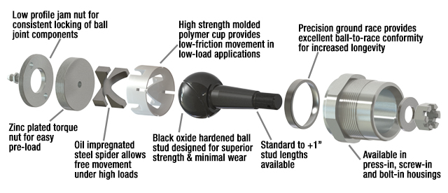
I bought model 1219-103 and discovered that the stud was 1/2" too short. Because they are rebuidable, this was easily fixed by buying the 9029-203 ball stud and installing it (note that I should have bought 1210-203B which comes with the appropriate length stud).
I liked the concept that they were rebuildable, but I wasn’t expecting to rebuild them before they were installed!
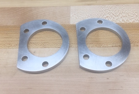
Pnut figured out that everything was off by 0.25" so he designed a custom spacer, I 3D printed a test for him and then he had several sets water jet cut out of aluminum. This is what they looked like after a little sanding.
They don't come with boots. The ones that came with the kit had different boots; one was perfect and the other wasn't. I'll post a part number when I find an appropriate replacement. You'll also want longer 2" screws to make up the height of the spacer.
You need two special tools (about $25 for both) to set the pre-load or rebuild the ball joints. The video below demonstrates how it's done.
How to Rebuild a QA1 Ball Joint - YouTube
The top of the ball is 0.25" closer to the ground which will lower the roll center a little which shouldn't hurt anything. Pnut took his car out for a spin and he liked the improvement... I let him comment.
I bought model 1219-103 and discovered that the stud was 1/2" too short. Because they are rebuidable, this was easily fixed by buying the 9029-203 ball stud and installing it (note that I should have bought 1210-203B which comes with the appropriate length stud).
I liked the concept that they were rebuildable, but I wasn’t expecting to rebuild them before they were installed!
Pnut figured out that everything was off by 0.25" so he designed a custom spacer, I 3D printed a test for him and then he had several sets water jet cut out of aluminum. This is what they looked like after a little sanding.
They don't come with boots. The ones that came with the kit had different boots; one was perfect and the other wasn't. I'll post a part number when I find an appropriate replacement. You'll also want longer 2" screws to make up the height of the spacer.
You need two special tools (about $25 for both) to set the pre-load or rebuild the ball joints. The video below demonstrates how it's done.
How to Rebuild a QA1 Ball Joint - YouTube
The top of the ball is 0.25" closer to the ground which will lower the roll center a little which shouldn't hurt anything. Pnut took his car out for a spin and he liked the improvement... I let him comment.
Scott
Lifetime Supporter
Cam,
The QA1 ball joint requires a lot more space under the control arm. This isn't an issue in front, but NFW will they fit in the rear. I plan to see if the Moog ball joints will work there. I think both pnut and Ken have a set, but I don't think they've tried to install them yet. If anyone has upgraded their rear ball joints I'd love to hear about it.
The QA1 ball joint requires a lot more space under the control arm. This isn't an issue in front, but NFW will they fit in the rear. I plan to see if the Moog ball joints will work there. I think both pnut and Ken have a set, but I don't think they've tried to install them yet. If anyone has upgraded their rear ball joints I'd love to hear about it.
Ken Roberts
Supporter
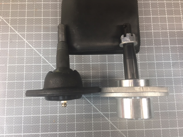
Here are some pictures of my findings with the Moog K6136 ball joint. They are almost identical to the factory supplied ball joint. As you can see in the last two pictures the Moog ball joint has a slightly larger spacing. It is approx 3/32" larger.
Moog on the left

Moog ball joint

Factory supplied ball joint

Moog on the left

Moog ball joint

Factory supplied ball joint

Ken Roberts
Supporter
The statement in the SLC Wiki (suspension section) that said the Moog ball joint has the same stud length as the QA1 is not accurate. The QA1 is 1/4" longer than stock. The Moog (as measured by myself, installed) is 3/32" longer.
Last edited:
Ken Roberts
Supporter
I installed them in the rear as well now. The rear ball joints were the same as the front. So my observations were identical. The Moog joints were 3/32" longer. To get the ball joint separator to fit/work I had to grind material off the top of the nose of the tool. This is shown in the first picture.

Here is an observation of all the original ball joint boots.The rubber at the bottom of the boot was squished out between the flange of the ball joint and the mating flange of the lower control arm. This is not good. It will interfere with the torquing of the 4 mounting fasteners. Once the boot dry rots in the future and shrinks the fasteners risk the chance of losing their tightness.


Here is an observation of all the original ball joint boots.The rubber at the bottom of the boot was squished out between the flange of the ball joint and the mating flange of the lower control arm. This is not good. It will interfere with the torquing of the 4 mounting fasteners. Once the boot dry rots in the future and shrinks the fasteners risk the chance of losing their tightness.

Last edited:
Ken Roberts
Supporter
I took the Moog boots and modified them by cutting off the steel flange. The first picture shows the boot as it comes. The second picture shows one of them after trimming with tin snips. I then carefully ground down the rest of the flange with a die grinder and then on a stationary sanding belt. They are a friction fit in the pocket of the lower control arm so a flange is not needed. Be careful not to overheat the rubber while grinding/trimming.


Ken Roberts
Supporter
If the 3/32" longer length is a concern then perhaps we could all go in on some spacers waterjet cut to .090" thickness.
A replaceable spacer is actually a good idea. Any galvanic corrosion between the aluminum lower control arm and steel ball joint will take place at the spacer and can be changed out in the future instead of damaging/weakening the control arm.
A replaceable spacer is actually a good idea. Any galvanic corrosion between the aluminum lower control arm and steel ball joint will take place at the spacer and can be changed out in the future instead of damaging/weakening the control arm.
Last edited:
Ken Roberts
Supporter
The rear ball joint, due to clearance restraints, requires a 3/4" box end tight clearance offset socket to torque to 55 ft/lbs (initial).
McMaster-Carr
McMaster-Carr
The statement in the SLC Wiki (suspension section) that said the Moog ball joint has the same stud length as the QA1 is not accurate. The QA1 is 1/4" longer than stock. The Moog (as measured by myself, installed) is 3/32" longer.
I wonder why our measurements differ slightly? Perhaps the joints were from a different batch, and this is acceptable variation?
I'll update the wiki to reflect this new understanding- thanks Ken!
For my car, I used the Moog boots when I installed the QA1 joints in the front. The Moog boot design looked very good to me compared to the original boot (which differed from the one you pictured above).I took the Moog boots and modified them by cutting off the steel flange. The first picture shows the boot as it comes. The second picture shows one of them after trimming with tin snips. I then carefully ground down the rest of the flange with a die grinder and then on a stationary sanding belt. They are a friction fit in the pocket of the lower control arm so a flange is not needed. Be careful not to overheat the rubber while grinding/trimming.
I just sandwiched them between the spacer and the control arm. They are a snug fit as you point out, but when I was installing them I wanted the added security of using the flange under the bolts, so I installed them with no changes.
The rear ball joint, due to clearance restraints, requires a 3/4" box end tight clearance offset socket to torque to 55 ft/lbs (initial).
McMaster-Carr
I haven't tried these in the rear, and I'm glad they fit in your car, but I would caution builders to check clearances with their car before using a spacer, or a deeper ball joint (like the QA1) in the rear, as the clearance between the bolts, or the bottom of the joint can be very tight, depending on the rim size.
If you have 20" wheels, you probably have plenty of clearance. Some 19" wheels, especially cast ones with a thick barrel, will foul the ball joint bolts in the rear if the bolts are installed with the bolt heads up (as opposed to the documented way to do it, with the bolt heads down). Even the factory-provided 19" wheels have minimal but acceptable clearances here. Cars with 18" rear wheels other than the CCW C10s will likely find interference so be sure to check your individual car for proper clearance.
"Acceptable" depends on your wheels. The CCW wheels, for example, are very rigid, and have very little deflection under load. You can get by with just under 1/8" clearance with these, but other lesser wheels, especially 3-piece wheels with spun rim halves generally have much more deflection. The 01 race car with such wheels saw more than twice as much deflection at the rim edge under load compared to the CCW forged wheels.
When substituting parts, always check both static and dynamic clearances. I've seen at least one case where at rest, there was clearance, but under load, a groove was being self-machined into a wheel barrel.
Ken Roberts
Supporter
Will, do you think the 3/32" difference in length is a concern (from a suspension geometry point of view)? I'm thinking it shouldn't be. I'll just install them as is without spacers
Will, do you think the 3/32" difference in length is a concern (from a suspension geometry point of view)? I'm thinking it shouldn't be. I'll just install them as is without spacers
I haven't stayed in a Holiday Inn recently, so that makes me no expert. :laugh: But I doubt if it makes that much difference. I thought that .250 was too much, hence the spacers. But I probably would have just gone ahead with them without spacers if I had measured just 3/32.
If your OCD gets control, you could conceivably model the suspension with a suspension modeling program. I've always wanted to see this done, but not enough to actually go through the effort of measuring the existing car, and doing the data entry. I'm sure that the camber gain curves are changed, as is the roll center. The question would be whether or not the changes are significant, or noticeable. My guess is that it wouldn't be, especially for a street-driven car.
I can tell you that the software I've been using test changes at the lowest increment of 1/16". The changes are being made on both sides and in a direction that I think doesn't translate to large angle movement. You could easily estimate the change with math also but I wouldn't sweat it.
Scott
Lifetime Supporter
I need to get my LS7 exhaust manifolds ceramic coated inside and outside. It seems that people have had good experiences with Jet-Hot and Central CT. Coatings. That said, technology changes and I'm wondering if there is anyone else I should be looking at or if someone has a preference between those two.
Similar threads
- Replies
- 10
- Views
- 10K
- Replies
- 4
- Views
- 5K