S2's Build Thread

Scott

Lifetime Supporter
IMG_7157.jpg


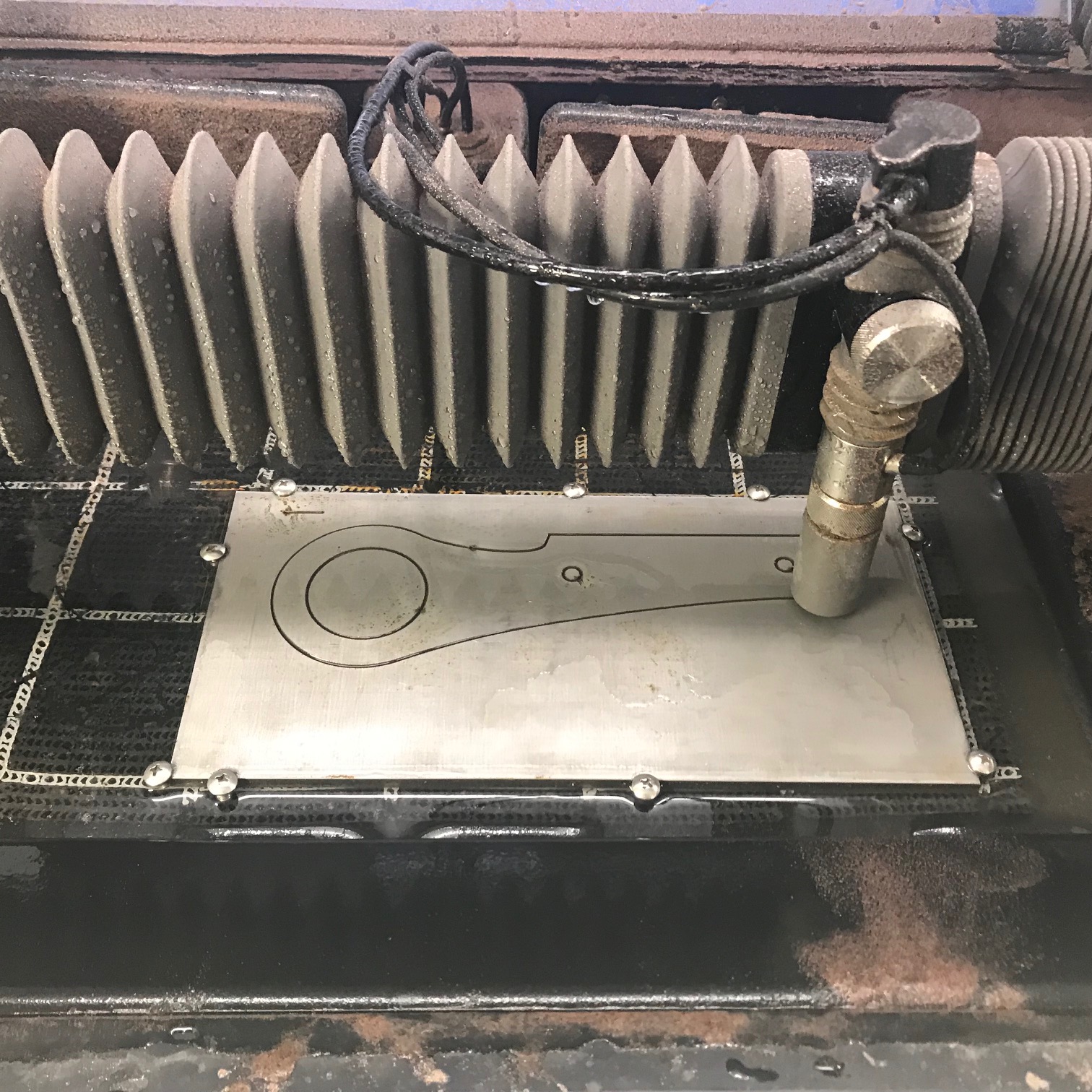
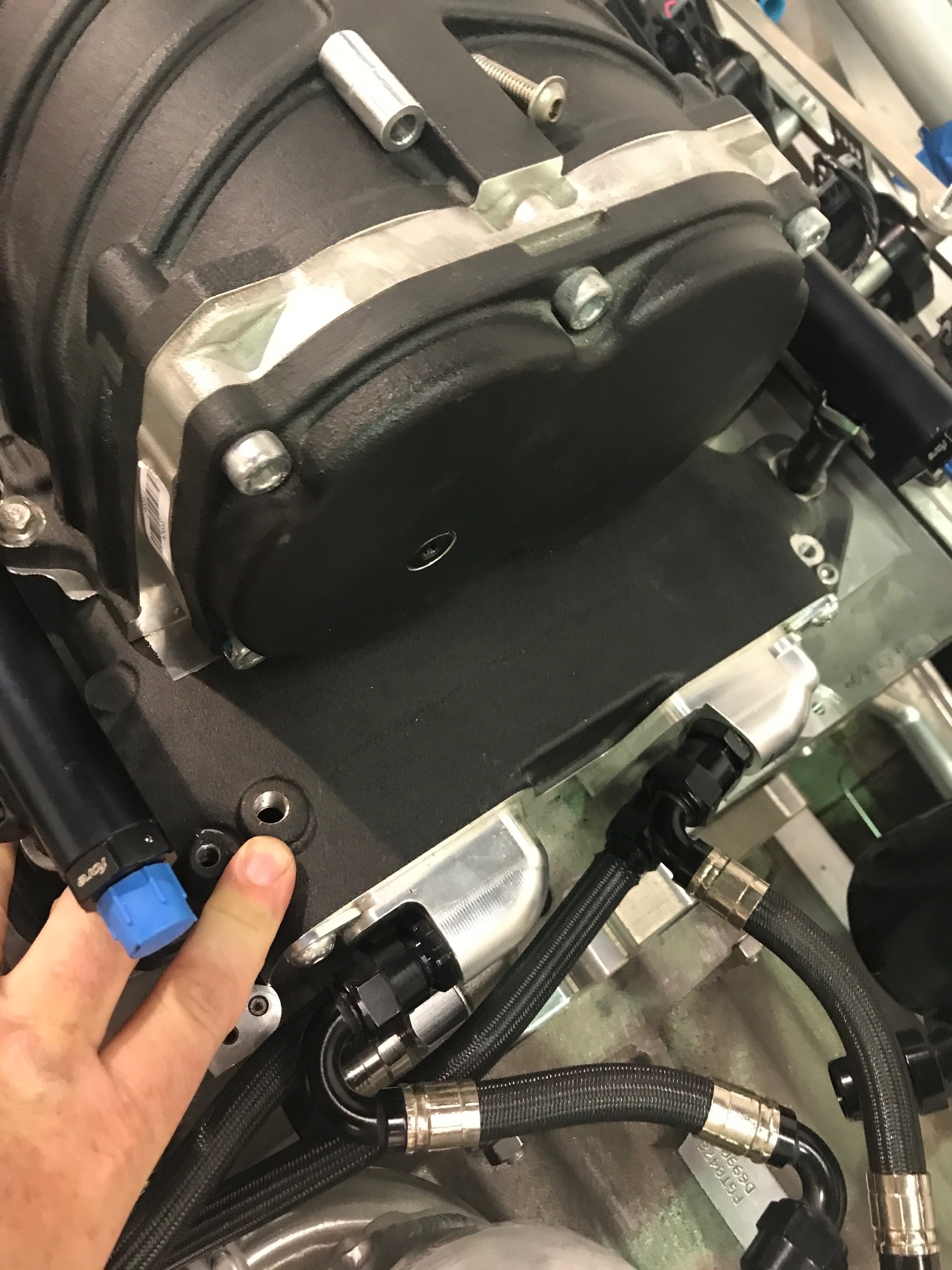
I cut the the front tow hook out of 1/4” cold rolled steel. At two hours and 42 minutes it was by far the longest cut that I have done. I was a bit nervous about having an issue in the middle of the cut which would waste a lot of abrasive not to mention the material because during a previous cut the Wazer stopped cutting all of the way through a piece of 1/8” stainless steel.

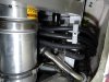
When this happens the water jet and abrasive bonces off the material in the direction opposite to the cutting head’s motion. Unfortunately the seam between the lid and the sides is not well sealed and some water and abrasive will escape. If you don’t catch this right away you’ll have a bit of a mess to clean up. While the mess is manageable, water will drip down the side and into the abrasive hopper which wrecks it (i.e., makes it lumpy which will cause a clog). I scooped all of the wet abrasive out using a specialized tool… I know that it looks like a serving utensil, but I would never use a kitchen implement in the garage;-)

IMG_7161.jpg

Specialized abrasive removal tool

The cutting stream’s bounce back when piercing doesn’t case any issues. I assume this is because it bounces back vertically into the cutting head.
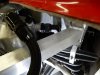
After running a test I determined that the abrasive flow rate was too low so I emptied all of the abrasive and used compressed air to ensure the abrasive feed tube was clear. After that everything worked fine. As can be seen in the picture below, the cut quality was outstanding. The cut consumed a whopping 53.4 pounds of abrasive. While that seems completely uneconomical, that’s $76.89 if you purchase by the bucket and only $24.03 if you purchase by the palette. Even the higher bucket price is about half of the minimum cut fee around here.

IMG_7158.jpg

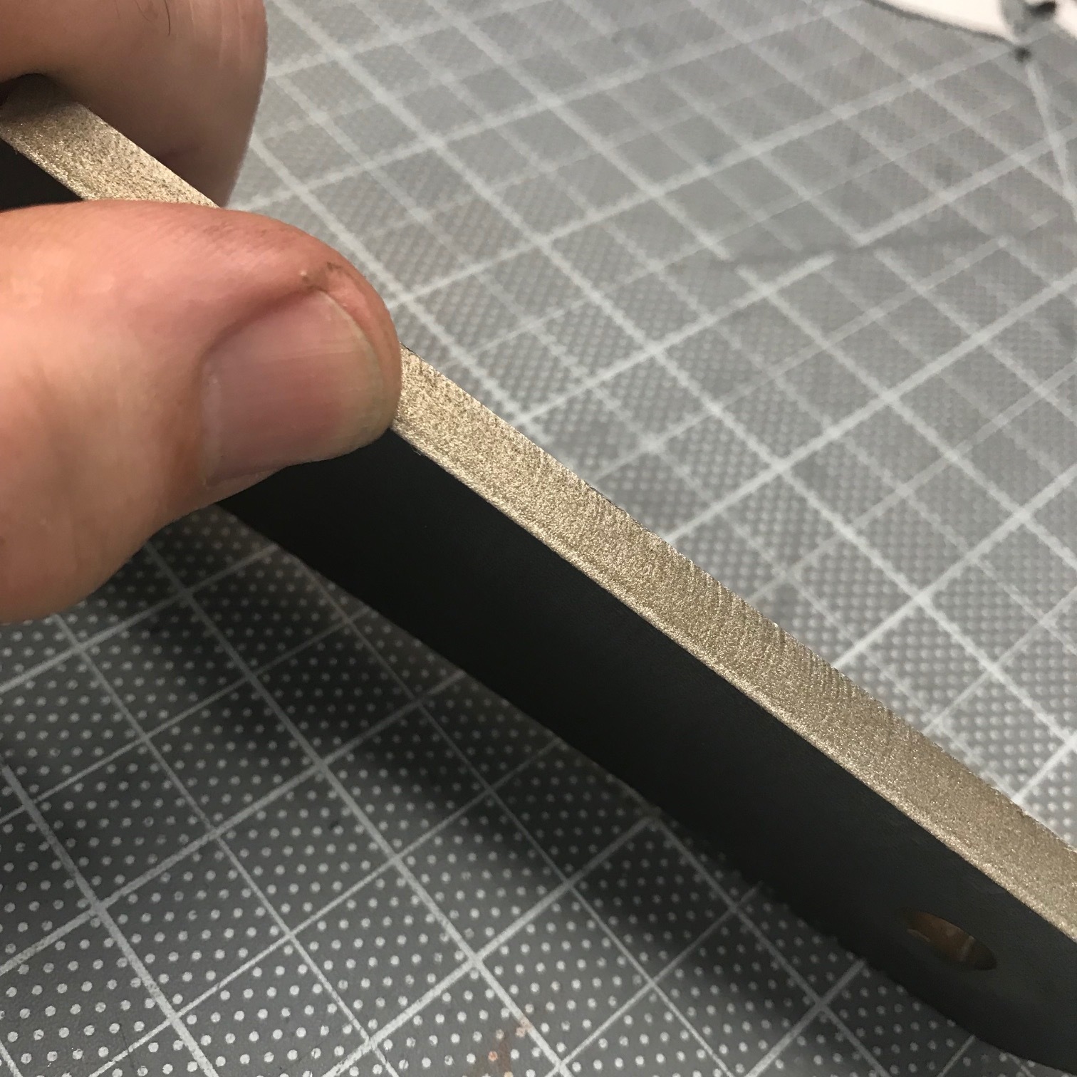
Excellent cut quality

IMG_7193.jpg

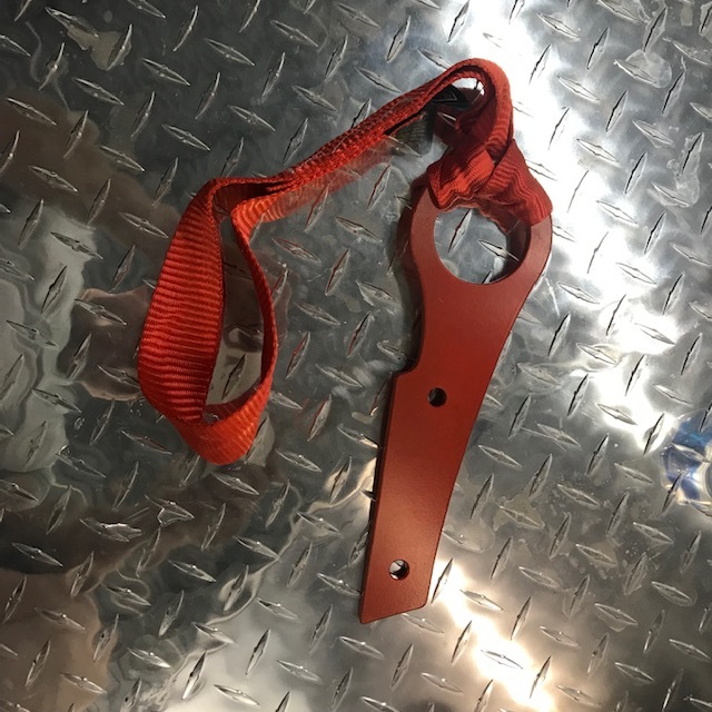
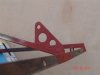
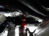
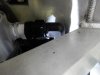
Temporary paint and soft strap

I cleaned up the edges with a mini sander and sprayed it with some rattle-can red (I'll powder coat it later). The short soft strap keeps the metal hook from marring the hook or diffuser.

A couple of takeaways:
  • Per the manual, stay in the same room as the Wazer when cutting. When the water jet is bouncing off of the material is makes a different sound which will alert you to look at it. Unfortunately, the piercing operation sounds the same so you need to look at the LCD panel to determine it’s piercing or cutting. If it’s cutting, you have an issue.
  • Wazer should have designed a channel into the top of the abrasive hopper so that water dripping down the side doesn’t contaminate the abrasive.
  • Wazer needs to add a feature that allows a cut to be restarted at a given place. If this cut had failed like the prior one did, it would have wasted over $100 of material and abrasive.
 

Neil

Supporter
Scott;

I took the easy way out; it wasn't as much fun as watching a piece being cut out with a Wazer, though. For a tow bracket I welded on a 1/8" tab from A & A Manufacturing. Part # AA-301-A.

https://www.aa-mfg.com/product/mounting-tab-2/

It cost all of $1.64. To tow, I clip a karabiner through the front hole and a nylon tow rope through the karabiner. Nylon stretches so starting off in tow is smooth and easy.
 

Attachments

  • Tow To Tech Inspection.jpg
    Tow To Tech Inspection.jpg
    507.2 KB · Views: 464
  • Tow Bracket.jpg
    Tow Bracket.jpg
    57.5 KB · Views: 498
Scott - I'm dying to see what you do with the bodywork at the rear end. How far in the future is that piece of the puzzle?
 

Scott

Lifetime Supporter
Neil, while it is fun to watch the Wazer cut thin materials (gaskets, thin plywood, etc.) watching it cut 1/4" steel isn't... 159 seconds to pierce and 0.214" per minute to cut. I'd rather watch paint dry because that would at least be quiet. I spent days looking at tow hooks and brackets and there wasn't anything that met my needs. Using a nylon rope makes sense given how quickly the recovery crews yank cars our of the gravel.

Chris, I haven't done anything further with the tail yet. In September I'm going to mock the exhaust and rear sway bar. At that point I'll validate that the diffuser will work as rendered. I'm starting to look for a place to CNC cut the foam and to help with bucks, molds and parts. If anyone has ideas, let me know.

I have been working on some mods to the nose. Specifically larger brake duct openings (I have heat exchangers for the intercoolers up front), a radiator outlet and hopefully some OEM headlights. The challenge with headlights is that the SL-C's nose has a lot more curve than every car that I can find. I bought damaged Ferrari 458 and Ferrari California headlights on eBay. I covered them with painter's tape and then packing tape before covering the lenses with fiberglass to capture the shape. I was able to lay the 458 "lens" on the nose and get a good fit. However, the light will be pointed directly into the ground. To validate this I bonded steel plates onto the top of the lenses and used a digital level to see how far off the angle was. As illustrated by the orange line in the picture below, the 458 light would need to raised ~5" to be at the correct angle... not going to happen with reworking the entire nose. The Ferrari California light was a lot closer, but would still require a lot of work. I'm having it scanned to figure out if it's feasible before I cut anymore holes;-)

99583

California on left and 458 on right. I'm pretty sure the 458 has less slope when mounted in the car.

99584

458 "lens" with digital level on top. Note how high the front is from the SL-C's nose. The California lens and light are sitting on the floor to the right..

99585

The orange line illustrates what would need to be filled to mold the light in.
 
Last edited:

Scott

Lifetime Supporter
I finished filler for the oil reservoir discussed in a previous thread. I replaced the back oxide screws with black anodized aluminum ones because I didn’t want them to rust and I created a design for the cap and had it laser etched.

The oil reservoir’s fill cap was cut off and replaced with a -16 AN weld bung. -16 fittings are huge and they were too close together to use a short piece of hose, so I had to create a bigger loop than I originally anticipated. I considered using a short piece of hard line, but I figured that the body would flex more than the chassis.

Since a dipstick won’t work, I bought an oil level sight tube kit from Peterson Fluid Systems which required more welding. I didn’t like how far the tube projected from reservoir so I replaced the female ORB weld bung and male AN adapter with a male AN weld bung. Lighter, half the parts and it sticks out less.

IMG_7272.jpg

Laser-etched cap & annodized aluminum screws

IMG_7278.jpg

-16 hose and fittings (nuts aren't final)

IMG_7279.jpg

Oil level sight tube

I spent a couple of hours trying to figure out how to fit the scavenge filter specified by Daily Engineering. It’s huge (9.7” x 2.5”) and it requires large -16 fittings. If the oil reservoir were located in front of the rear tire it would be a lot easier, but it’s against the firewall and it’s really tight. I found an XRP filter that 3’ shorter so I’m going to see what Daily thinks about using it.
 

Scott

Lifetime Supporter
Dan,

Good question. My plan is to cut thin strips of 1/8" self-adhesive rubber and stick it to the underside of the carbon fiber ring. This will allow water to flow freely. Then I'll drill a few holes in the body and the aluminum mounting plate. It will all be covered by the ring so none of it will be visible.

There's no way to drain the hex recesses in the screws which is why I swapped the black oxide for anodized aluminum.
 

Johan

Supporter
Scott,

Speaking of drain, I was recently changing the oil in the engine. Having filled my 8qt tank with 8qt (I’m sure) I only got 6qt out.
As it turns out the scavange filter and the -16 hoses together with thermostat, oil cooler and 2:nd oil filter contains at least 2qt.
So next time I take the engine out I’ll install drainplugs in the scavange filter and the oil cooler fittings.
Doesn’t matter if you run the pump with a drill, it will not scavange the remaining oil out of the system, you have to drain it.
 

Scott

Lifetime Supporter
Johan, I'm interested in how you ran the scavenge filter and lines. With the location of my oil reservoir it's really tight. The recommended Peterson 400 series would require several 90-degree and one 180-degree fittings. XRP makes one that is 3" shorter and should be more manageable. The 01 race car had a rectangular filter box welded to the reservoir (see picture below), but Peterson no longer makes it. Note that my reservoir is located up against the firewall so it's a lot tighter than the 01 car.

One of the SL-C race teams ran into the same issue and decided to run without a scavenge filter, so I guess I'm in good company with this challenge. In any event, I'm hoping you did something that I haven't thought of or someone knows where I might find a different -16 filter; a rectangular one or one that could be welded to the reservoir.

99840
 

Johan

Supporter
Scott,
It´s a bit tight but it works. All hoses and fittings according to Bill D.
Did you send that wiper mount?
 

Attachments

  • DSCN0966.JPG
    DSCN0966.JPG
    749.4 KB · Views: 397
  • DSCN0967.JPG
    DSCN0967.JPG
    799.3 KB · Views: 339
  • DSCN0969.JPG
    DSCN0969.JPG
    617.5 KB · Views: 388
  • DSCN0970.JPG
    DSCN0970.JPG
    660.7 KB · Views: 348
  • DSCN0971.JPG
    DSCN0971.JPG
    632.9 KB · Views: 351
  • DSCN0972.JPG
    DSCN0972.JPG
    740.5 KB · Views: 383

Scott

Lifetime Supporter
Johan, I had someone ship the wiper module on Friday. I need to validate that it was done. I asked him to get a tracking number, but there's a bit of language barrier;-) I'll check with him tomorrow.

Thanks for the pictures. I try not to use hard 90s where on pressurized lines. I have Bill's recommendations on line and fitting sizes. Is he OK with a hard 90 on the scavenge line?
 

Scott

Lifetime Supporter
Pressure+Regulator.jpg

I converted the fuel rails from a deadhead-return-style to a flow-through-return-style configuration to better support my power levels. While doing this I replaced all of the barbed fittings with AN fittings. Most SL-C builders seem mount the pressure regulator to the firewall or chassis, but I decided to mount it between the fuel rails on the supercharger. This results in less hose and I think it looks cool because it fills in an otherwise empty space which is visible in the rear window. That said, it was a lot more work than mounting it to one of the standard locations with the provided bracket.

The primary challenge was figuring out how to securely mount the regulator so that I could use hard fuel lines. There are two casting holes in the intercooler which I tapped for 1/4”-20. I then used 1/8” aluminum to fabricate the mounting plate which provided an opportunity to use my dimple dies. Yeah, I know they’re more commonly seen, and often overdone, on hot rods, but I think they’re cool. Both the aluminum monocoque and the dimple die originated in the aviation industry, so they aren’t out of place. Abe did a nice job welding it together.

Self-adhesive 1/4” rubber was used to pad the plate above the cast boss for the vacuum reference port and to help dampen vibrations. This finalized the height of the plate and two aluminum spacers were turned on the lathe to fit between the holes tapped into the intercooler and the plate. The two extensions at the back of the plate are wedged under the supercharger and are intended to help keep the plate in place.

Abe had two pressure regulators from Fore Innovations; a F1i which is two tone (raw aluminum and black) and a F2i which is all black. I prefer the appearance of the former, but the latter has superior internals, specifically a ceramic/stainless valve and a fluoropolymer coated spring. After confirming with the manufacturer, we swapped the internals.

Fuel pressure gauges are bulky. This normally isn’t an issue, but mine is on display in the window so I spent several late nights looking for a thinner one (see comparison picture below).

58153028812__5B9991B0-F5F8-408C-9E5F-E627B7A2096F.JPG

Mounting hole (left) & vacuum reference (right)

IMG_7124.jpg

Mounting plate

IMG_7130.jpg

Mounting plate installed

IMG_7139.jpg

Thin (left) vs. standard (right) fuel pressure gauge

I wasn’t able to remove the 1/4” NPT plug from the vacuum reference port. Worrying about stripping something in an important part is one of the most stressful parts of building a car… and the supercharger is both important and expensive. I tried using a hex-bit socket and a 3/8” impact gun to no avail. I then made a simple heat shield (a hole in scrap aluminum) to protect the paint, heated the plug with a torch and tried again to no avail. If it was going to strip, I wanted Abe to be vested so I let him deal with it ;-) He heated and wailed on it with the 3/8” gun and it didn’t budge. The last attempt before pulling the super charger off and drilling it was more heat and a 1/2” impact gun. Fortunately, that worked! I replaced the plug with a stainless steel barbed fitting.

The fuel lines were fabricated out of aluminum. I’m going to look for a thinner vacuum line, but this part of the car is done until final fit up. The next step is to install the surge tank, high-pressure pump, E85 sensor and fuel filter between the fuel rails and the low-pressure fuel system.

IMG_7141.jpg
 
Last edited:

Johan

Supporter
Johan, I had someone ship the wiper module on Friday. I need to validate that it was done. I asked him to get a tracking number, but there's a bit of language barrier;-) I'll check with him tomorrow.

Thanks for the pictures. I try not to use hard 90s where on pressurized lines. I have Bill's recommendations on line and fitting sizes. Is he OK with a hard 90 on the scavenge line?
I don’t know what Bill thinks about hard 90 fittings, but it is the same flow as the pressure side and there the smallest line is -10.
If you look down in the tank with engine running, it’s not that much oil flowing into the tank. I would be more concerned with a smaller more restrictive scavange filter.

Do I owe you some money for the shipping? Pls let me know.
 

Scott

Lifetime Supporter
The SL-C has been around a while and still looks great, but I’d like to modernize it a bit. Before I embark on changing the tail as discussed in a previous post, I’d like to go through the design, CNC cut male buck, fine tune buck, make female mold, make part, blend part into body process a couple of times on simpler parts. Specifically, the rear side scoop and roof scoop.

IMO the rear side scoop is a little small and likely doesn’t capture a ton of air — that said, I’m primarily focused on aesthetics. So I want a larger vent and to dish the side of the car like many modern cars. While dishing the doors would look great, that’s a lot more work than I want to even consider.

I’m also thinking about changing the roof scoop. I’ve always had mixed thoughts about it ranging from it’s cool to it’s a bit of a bubble sitting on top of a bubble. I’m thinking about shaving it off or making it more aggressive (i.e., rectangular). I was leaning towards shaving it because it’s cleaner and I didn’t think it was very functional… that discussion led to pnut’s recent post which indicates that at road speeds it appears to work pretty well.

Kevin did such a great job on the tail that I had him do a bunch of 2-D renderings. Here’s a bunch of variants.

Side-Variations-Full-Layout.jpg


Variations--Front-Vent.jpg


Variations--Rear-Vent.jpg


Variations--Roof-and-Front-Facia.jpg


Currently leaning towards this one..
SLC-Sidemods.jpg
 
Great stuff!

I'm a big fan of the 2.8 rear vent. I attempted to make a "2.1 simple scoop cover" with an angle that matched the door but didn't have the mold making skills to do it justice. I struggled with how to shape the arch and tie the horizontal and vertical planes together. It also looked a bit too short in my mock-ups.

Seeing the 2.8 rendered, that's a really nice way to update the side of the car and make it pop with the different colored scoop cover - looks fantastic! The slash ties in nicely with the angle on the door and breaks up the side some more. I also like that it ties in height-wise with the opening behind the front tire. Pushing the upper surfaces up closer to the body joint does a lot to emphasize the side contour and makes it a closer match to the bottom surface. It also pulls your eyes away from the green house bubble so you give the bubble and side contour equal attention. Pushing the vents up and down really changes the look!

I don't know if you've played with the front end but I like how there's that very subtle curve that turns back as it comes down and gives the nose of the car a little more emphasis. It's a bit too "blocky" and vertical in its current form, I used a paint line to try and create the look of a relief on mine.
 
Scott

I would not have thought the larger front and rear scopes/vents would make that dramatic a difference in the car. I really liked the combination of the two vents slanted backward.

Nice renderings. The wing seems very familiar to me.
 
I'm with you Scott, 3.1 is the one. If you moved the features up to incorporate/eliminate the front and rear clip panel cut lines, it would further clean up the side and eliminate much of the body gap challenges from the area. All at the cost of more engineering / body mods to secure/locate the spider to the clips. With those side scoops you could probably move your radiators to the hips if you wanted (keep the cabin cooler).
 

Scott

Lifetime Supporter
I should have put the image series in order (i.e., 1, 2, 3, 4). My choices so far are:
1.2 (roof scoop delete)
2.8 (angled farther back two-tone rear vent)
3.1 (taller front vent)
4.3 (dual canards)

I don't know if you've played with the front end but I like how there's that very subtle curve that turns back as it comes down and gives the nose of the car a little more emphasis. It's a bit too "blocky" and vertical in its current form, I used a paint line to try and create the look of a relief on mine.
Cam, we spent some time trying to deal with that area. Making the front tire vent doesn't look right with the recessed curve in front of the tire. That's why 4.4 fills in that area. According to pnut that recess on the nose helped with aero around the front tire and it also adds more surface area to the splitter which can only be a good thing. Do you think the front vent would look better if the curved piece next to the tire more closely followed the curve of the tire and was a bit thinner?

I really liked the combination of the two vents slanted backward... The wing seems very familiar to me.
Dan, are you saying that your preference is 3.4? The wing is an Aeromotions dynamic split wing.
 
I'm amazed how much those changes made to the profile of the car, love it. Also REALLY makes me want tinted windows. For what it's worth I like the angled back vents with no scoop and roof bubble delete.

1.2
2.3
3.5
4.1
 

Joel K

Supporter
Very nice renderings

My first pass I like:
1.2
2.8
3.1
4.1

If possible, would like to see a roof scoop mounted a bit further back like the GTP Jaguar.

E6F7BAD6-E5E3-4C1D-9073-23CA5513E2FF.jpeg
900C6868-A626-485D-9A76-547EE3A1A318.jpeg
59517AF9-E329-42D6-9E03-6B42B2FC0A42.jpeg
 
Back
Top