S2's Build Thread

Scott

Lifetime Supporter
Mesa, I think you're talking about 2.5 above, but with the black side scoops. Below are three renderings with increased vent heights:

A: requires no changes to the front vent

B: provides room for the aero catches in the standard location;

C: IMO this version looks best. As you point out the visible fiberglass is easier than B because there is no need to maintain the thin section of body or the panel gaps above the vent. The big question is how to get the aero catches to work. I think the rear one could be slid back and hid in the vent. The front will be a challenge.

I'm traveling until the end of August so I can't look at the car to see how complex it would be. If you have any pictures of how you solved the problem, please post them.

I have a custom C&R radiator/shroud up front, so I'm not going to consider moving the cooling to the rear.

100104
 
Scott

After pondering the drawings some more, 3.1 or 3.4 are my favorites. I see following the front wheel well does add to the front better but the symmetry of the angles looks impressive as well. Are you planning to make the mod? How will you maintain structural integrity?
 

Scott

Lifetime Supporter
100807


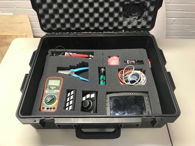
I took a six-week vacation with the family and, fearing build withdraw, I made a man bag to bring some electronics along. Needless to say my wife wasn’t happy — something along the lines of “NFW are you bringing that!”.

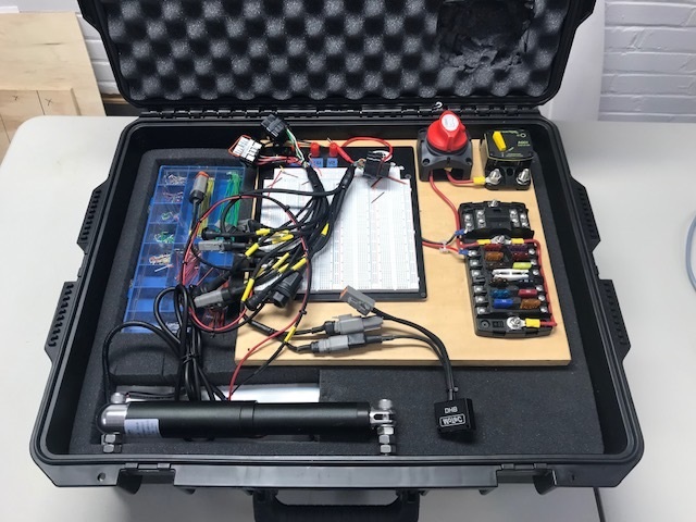
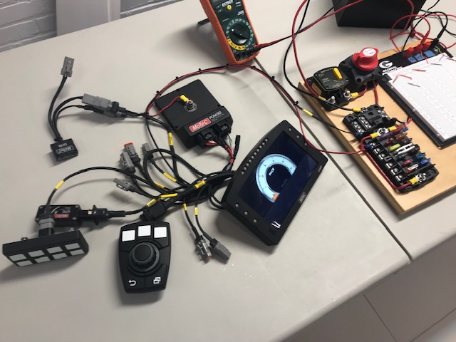
Joel made a bench harness so that I could start to get my brain wrapped around the MoTeC display, Power Distribution Module (PDM), keypad, rotary keypad, Dual Half Bridge (DHB) and CAN bus. The test harness is first rate; Deutsch connectors, Raychem DR-25 sheath, labels on everything and detailed documentation.

My plan is to focus on the basics and leave all of the complex ECU and tuning stuff to the pros. Even so, MoTeC isn’t geared for DIY’ers, so Joel is providing tutoring lessons via a remote desktop application— my kids think it’s hilarious that the old man still needs tutoring.

IMG_7692.jpg


IMG_7694.jpg


IMG_7695.jpg


IMG_7696.jpg


One of the primary objectives with a MoTeC setup is to replace as many physical fuses as possible with PDU outputs which have configurable current limits, automated retries, logic and logging. For this reason, the harness powers the display via a PDU output. The first step was to configure the name of the output. Like software, it’s a good idea to provide robust names. Since it’s part of the bench tester and it powers the C127 display, the keypad and a spare power connector, I named it “Output.BenchTester.C127/Keypad/Spare”. To power it, I simply created a condition as can be seen in the snippet from the PDM Manager below. When then PDM has power, the display, keypad and spare power connecter have power.

100806


I didn’t get very far with things, mostly because I had a poor internet connection which made the remote sessions difficult. However, I was able to get the keypad buttons to activate turn signals, the hazard and to activate the DHB.

Now that I’m back home, I’m going to get things kicked into high gear!
 

Scott

Lifetime Supporter
Are you planning to make the mod?
Dan, I'm going forward with variant 2.6-A3, which looks the best, but requires the most work. Funny how it always seems to work out that way.

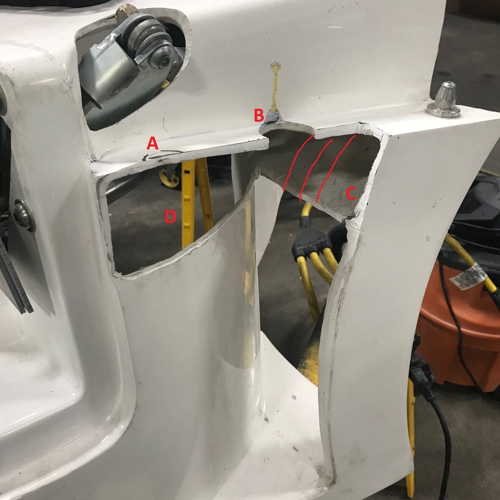
Today I made some initial cuts to implement the front vent… there’s no going back now! The AeroCatch and rear locating pin (A) were completely removed. Filling the curved vertical section (D) will be easy. I just need to bolt a curved non-stick piece of plastic to the outside and patch from the inside.
IMG_7712 Annotated.jpg

I left a portion of the flange that the nose sits on in place because the bottom side of the nose flange needs to clear the door hinge and the side of the spider when it is raised and lowered and something needs to seal the nose from the exterior. This flange will likely get cut back further and I’m wondering if I should create a large fillet to blend its underside into vertical section D.

The AeroCatch will fit into section C if it’s oriented transversely. However, that orientation places the pin more inboard than desirable which may cause the strike pin to scrape the side of the spider. The factory body fitment had that issue on the right side and the scrapes can be seen in B. For this reason, I’m going to replace the AeroCatch with a Quick-Latch QL-35. Even if I trim the flange off of the end of the AeroCatch, the center of the pin is 1.5” from the edge whereas the Quick-Latch is 0.9” with the flange in tact. In addition, the Quick-Latch installs with a single 1.25” hole saw whereas the AeroCatch requires a more complex oblong cutout and six mounting holes. Each Quick-Latch is rated for 500 pounds, so they should be more than strong enough.

100941


The biggest question at this point is what to do with piece C. If left as is, I will need to reinforce it (glass it to the curved vertical piece) and close the curved back edge (red lines). IMO it will look bulky and getting the back edge finished properly will be tricky. Another option is to raise piece C. The Quick-Latch requires a minimum depth of 1.2” which would allow me to reduce the distance to the part line by at least half. Getting the curved back edge to look right would be easier because it’s smaller and less visible. That said, I’d need to make a simple mold. I ordered a set of Quick-Latches and I’m going to reflect on things before cutting any more.

The door consists of an inner and outer shell which are bonded together at the factory. Fortunately, there is a fair amount of space between the two pieces which allowed me to cut the outer shell. I ground the dark-gray adhesive on the front edge because I assume that epoxy/fiberglass is stronger and I’m not sure how well the adhesive would blend with fiberglass or hold paint. As can be seen in the profile picture, there is plenty of room for epoxy/fiberglass to add strength and micro balloon mix to create the profile. The top edge of the door is thin near the top of the cut, but I can easily add fiberglass to the inside of the door there.

100943

Lots of adhesive on edge

100944

Most of adhesive ground off

100945

Room for epoxy/fiberglass and micro ballon mix
 

Scott

Lifetime Supporter
I spent a lot of time looking for a fuel pump with the following requirements:
  • 1,000+ HP; it’s gotta have the juice.
  • Brushless: Heats the fuel less and consumes less power.
  • PWM’able: No way do I want to be sitting at a light with the pump pushing over 120 gallons / hour at 42 psi. That will heat the fuel and if something comes loose I want to be flowing as little fuel as possible.
  • In tank: Reduces external plumbing and keeps the pump cool.
  • Flange-mount: No brackets, clamps, hoses or wires dangling inside of the tank.
  • Ethanol Compatible: More power and lower operating temperature.
While many pumps met most of the criteria, the brushless/PWM’able combination was the limiting factor. At some point during my search Radium announced a surge tank designed for the FUELAB 92902 which met all of my criteria. It’s rated to 1,800HP and has an integrated motor controller. This allows me to simply connect it to one of the PDM’s PWM outputs.

Great! I immediately ordered one… not so fast. Apparently FUELAB, chasing bigger HP numbers, changed the height of their pump twice which required Radium to change their surge tank twice. So, after over a year of waiting, I finally received the pump and the surge tank.

101002


Radium provides a filter which bolts to the bottom, an o-ring and a retaining ring with bolts — so about three minutes to install it into the surge tank.

I fabricated an aluminum bracket for the surge tank and attached it to the 2” x 2” tubes with six 1/4”-20 nutserts, two of which capture the surge tank. Four additional 1/4”-20 nutserts mount the surge tank to the bracket. I will fabricate a heat shield to protect it from the exhaust manifold.

101003


I also mounted my super trick fuel filter which I posted about here. Man, it feels good to get that out of the box and mounted to the car!!! If you’re wondering what the trio of holes are to the right of the fuel filter are, they are specifically designed to reduce harmonic engine vibrations from disrupting fuel flow through the filter OR I mounted the filter in the wrong place and now need to weld the holes shut;-)

101004
 

Joel K

Supporter
Very nice setup Scott, how are you going to control the PWM pump, with Fuelab’s electronic regulator, the engine ECU, or some other way? Just curious.
 

Ian Anderson

Lifetime Supporter
Neat looking setup.
What GPH / LPM is the pump rated at in order to support their 1800 hp?


What Low pressure pump will you run to keep the radium unit full?

Cheers
Ian
 

Scott

Lifetime Supporter
how are you going to control the PWM pump
Joel, I will control it via a MoTeC ECU. If I wasn't going in that direction, I'd take a serious look at Fuelab's motor controller. Since the motor driver is integrated into the pump, the controller is small.
101033

What GPH / LPM is the pump rated at in order to support their 1800 hp?
Ian, their marketing indicates:

190 GPH at 45 psi
720 LPH at 3.1 bar

However, every pump has a serial number and comes with a printed certification sheet. Here's a scan of mine:
101034


Looking at the results, my pump flows enough fuel for 1,800HP at around 75 psi, assuming that gives you enough boost headroom.

What Low pressure pump will you run to keep the radium unit full?
Ian, I'm a little over 1,000HP so I don't need to worry about feeding a 1,800HP monster. Assuming a Brake-specific Fuel Consumption (BSFC) of 0.65 at wide-open throttle (WOT)

GPH at WOT = (1,000 * 0.65) / 6 = 108.3

I used a Holly 12-125 because it worked well for my layout (it's vertical) and it seems to have a good track record. It is rated at 125 GPH free flow and 110 GPH at 7 PSI. So, In theory it can keep pace with WOT consumption if the pressure is in the surge tank is around 7 PSI. That said, I can't imagine applying 1,000HP for long in a SL-C, particularly in a sweeper that starves the low-pressure pump.

Radium's documentation "generally recommends a [lift] pump with a rated flow of 400+ LPH." That's 106 GPH which a little less than the Holly's spec.
 
The next step is to wire it up and test it. Apparently you need both calipers plugged into the ECU for it work.

Scott
Awesome build and write up.
How did you get on with the HiSpec EPB in the end, did you get as far as wiring up ? also on caliper mounting the clearance looks tight to the disc, is it threaded (M10?) or does it need a nut on the disc side of the fitting?
 

Scott

Lifetime Supporter
How did you get on with the HiSpec EPB in the end, did you get as far as wiring up?
The initial unit didn’t close properly when I bench tested it. I shipped it to them for repair and as far as I can tell everything worked properly during the subsequent bench test. Wiring it is trivial because everything has connectors. The harness even includes a small button. So, you only need to plug a few things together and supply power.

I haven’t machined the bracket yet. At this point, I’m waiting to receive the upgraded uprights from RCR. I doubt that the new version will change how I make the bracket, but I just want to be sure.

the caliper mounting looks tight to the disc, is it threaded (M10?) or does it need a nut on the disc side of the fitting?
It mounts to the bracket with two M10 screws which thread directly into e-brake with a reassuring amount of thread engagement (~38mm / 1.5”). As you point out there is no room for nuts and therefore there is no issue clearing the rotor. I plan on safety wiring the screws.

Was wondering how good their control unit it is, I asked the Customer Service guy a few questions and the answers left me with some doubts, I am sure it will work, but did sound like a bit of a compromise. 2 areas they were not clear on was the 2 optional connections.
There are three optional wires; ignition control input, wheel speed sensor input, and signal output for dashboard handbrake warning light. The first two are safety features beyond the required two-second button-hold time to toggle the brake. Time will tell how well it works, but it seems like a well engineered product and I don’t see any compromises.
 

Scott

Lifetime Supporter
Neil,

I also noted that the x-axis label was missing and I agree that it should be there. I assumed that when they added the Max/Reduced Speed legend they accidentally wacked the label. However, it only takes a few seconds to conclude that it’s psi. Furthermore, the certification states the serial number, the test date, the person who performed the test, the test media, the density and temperature of the test media, the voltage, and the version of firmware. That doesn’t seem like a company that’s looking to mislead anyone or obfuscate anything. In fact, the graph demonstrates that my pump performs ~12% better than the number cited on the Radium site which is another indicator that they aren't quoting "marketing" numbers. I was sure that the x-axis was psi, but in response to your post I called them to confirm and to let them know they should fix the oversight. Whatever suspicions you have with respect to the graph are unfounded.
 
Last edited:

Scott

Lifetime Supporter
I plan to run both 93-octane pump gas and E85. In a previous post I discussed my fuel pump requirements assuming a Brake-Specific Fuel Consumption (BSFC) of 0.65 at wide-open throttle. However, ethanol only contains 82,000 BTU per gallon whereas gasoline contains approximately 115,000 BTU per gallon which means that ethanol has a higher BSFC. Since ethanol contains 40% less BTUs per gallon you need 40% more fuel to obtain the same power level! The following are rule-of-thumb BSFCs for different fuels in a forced-induction application:
  • Gasoline: 0.60 to 0.65
  • E85: 0.84 to 0.91
  • Methanol: 1.80 to 2.00
So my engine running on E85 at wide open throttle requires 152 GPH. My high-pressure pump will handle that volume, but I’m now considering a low-pressure pump upgrade. I’ll also need to determine if I need to upgrade the fuel injectors.

To enable the ECU to change the tune on-the-fly based on the amount of ethanol I installed a ethanol content sensor (Continental 13577379) which is apparently widely used by OEMs and tuners. The inlet and outlet are straight aluminum tubes with a raised ridge and I wasn’t sure how to connect an AN fitting to it. Fortunately, Fore Innovations (and I assume others) offers AN Male to EFI Female Adapters.

101231


To install them, you carefully remove the retaining clip, slide the adapter on the tube until it hits the ridge and reinstall the clip. The clip is on the far side of the ridge which pulls the adapter into the ridge locking it into place. This applies pressure to an internal o-ring that is sandwiched between the adapter and the ridge, thus creating a leak-free interface.

I considered mounting the sensor to the backside of the aluminum heat shield between the exhaust manifold and the chassis, but I wanted to be able to remove the heat shield without touching the sensor. So I fabricated a bracket to mount it under one of the 2” x 2”s.

101232


101233
 

Scott

Lifetime Supporter
Thanks Chris. I think I'm 20% research, 20% change mind, 40% analysis paralysis, 10% redo and 10% finish;-) I need to get more done!

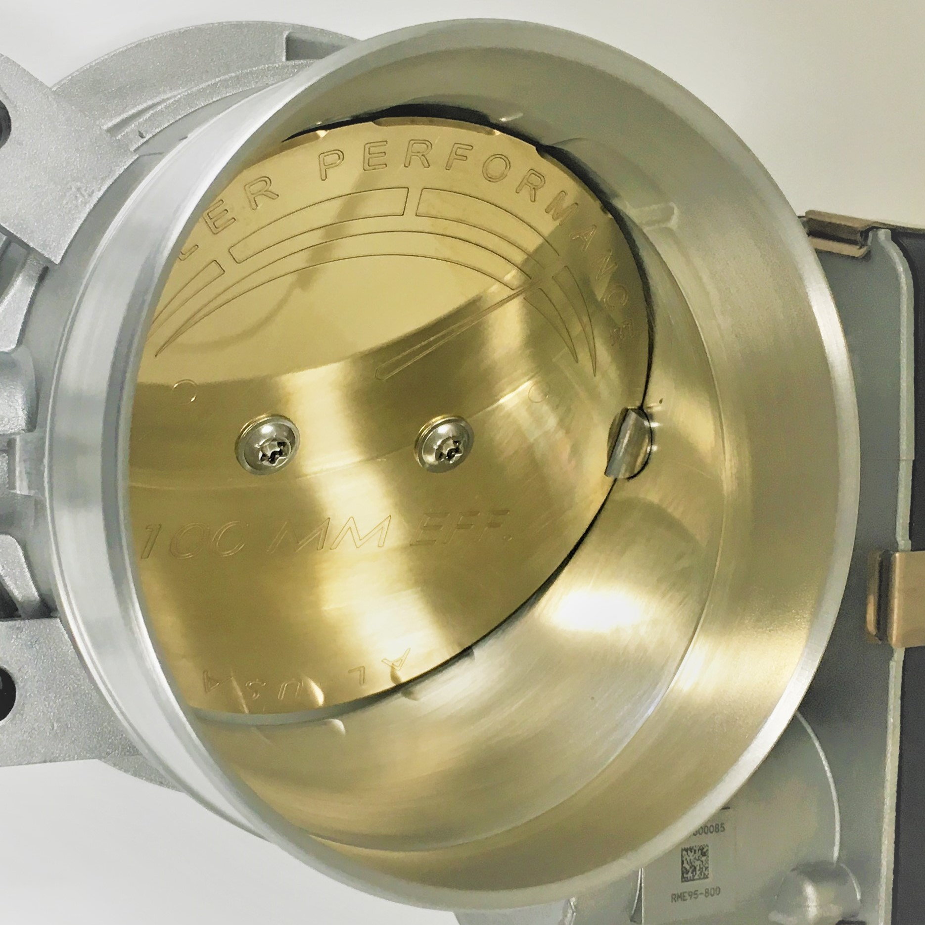
Redoing is a good segway to my issues with the induction system. The induction tube was hitting the tail and created a small crack in it. The ID of the weld flange mounted to the supercharger snout created an abrupt transition and it was too close to the supercharger’s o-ring — we don’t wanting that getting sucked in by accident. The LS7 throttle body was large and in the way and there no straight section long enough to mount a mass airflow sensor (I might have a blended MAAF/MAS tune).

I wasn’t sure what to do about it until Allan mentioned pointed out how much smaller the LT5 throttle body was. It’s dimensionally much smaller (see photo below), 32% lighter (2.24 vs. 3.29 lbs.), has a larger diameter (90 mm vs. 95 mm ) and it was designed for a supercharged rather than a naturally aspirated engine. Since I ‘m using a MoTeC ECU there won’t be tuning issues due to a different throttle body.

Of course, I mistakenly ordered a ported LT4 throttle body from Katech which means that I have I now have three throttle bodies. All too often, the third try seems to be the charm! In any event, if anyone needs a LS7 or an LT4 throttle body I’ll cut you a deal.

I spent many hours searching for the correct weld flanges. There are a lot of LT5 adapters out there, but I couldn’t find anything that met my requirements so I designed custom ones. Both have an internal recess to ensure that tube remains concentric with flange ID. The supercharger snout flange smoothly tapers the 4” tube into the snout and the throttle body flange has a groove for an o-ring. One-off CNC parts are spendy and can have long lead times so I 3D printed a couple of prototypes. As can be seen in the photo below, the fit was tight enough to hold it in place so long
as you don’t bump it. Abe was able to use them to mock the tubes, but he suggested that I beef up a few areas to prevent warping when welding.

101252

LS7 (top) and LT5 (bottom)

101254

3D-printed prototype flange fits well

101255

Supercharger snout flange

101256

LT5 flange; tube side


101257

LT5 flange; o-ring seals against throttle body

The next step is to find someone to CNC machine them… I’ve been thinking about buying a machine for years, but that might push my wife over the edge. Once I get the flanges machined and the tube between the supercharger snout and throttle body tacked in to place, I’ll need to scallop the upper 2” x 2” chassis rail to enable the tube to clear the tail.
 

Ken Roberts

Supporter
Scott if you want to take the LT5 throttle body one step further I'd recommend reading this....


His website has a great technical write up....

 
Back
Top