Stephan's SLC Build Log

Markus

SPRF40
Lifetime Supporter
Naja, sei nicht so bescheiden. Ich glaube Dein "kleines" Projekt ist hier im Forum schon vorne mit dabei und für deutsche Verhältnisse...... der TÜV lässt Grüßen . Freue mich auf Deine weiteren updates.
___________________________________________________________________________________________________________________________________________

Well, don't be so modest. I think your "small" project is high level here in the forum and for German conditions ....... the TÜV sends his regards . Looking forward to your further updates.

Regards vom Bodensee
Markus
 

Stephan E.

Supporter
First test fitting. Seems that all that measuring paid off :cool:
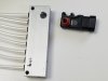
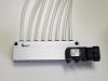
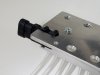
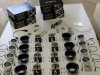
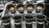
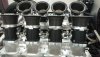
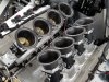
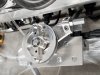
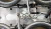
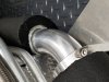
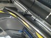
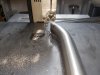
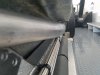
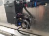
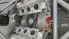
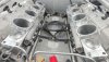
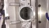
. The billet fuel rail are a nice match. I wanted to mention that the throat of the intake runners at the head entry are almost 3 in. wide. It does not come across since there is no dimensional reference point. I am afraid that there will be some sort of fuel consumption involved here.
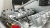
 

Attachments

  • DSC_0328.JPG
    DSC_0328.JPG
    352.1 KB · Views: 595
  • DSC_0312.JPG
    DSC_0312.JPG
    354.4 KB · Views: 590
  • DSC_0329.JPG
    DSC_0329.JPG
    357.5 KB · Views: 489
  • DSC_0309.JPG
    DSC_0309.JPG
    388.6 KB · Views: 436
Last edited:

Stephan E.

Supporter
Every time the SLC is in the driveway it causes folks to stop by and ask questions. One in particular besides how fast, what is it, how much HP, how much does it cost etc. The question is how it will sound. All I can say as of this point is that I am trying to achieve what made me do this in the first place. Watch the video of the car that did it to me 30 years ago. 6.3 liter V8, 32 valve naturally aspirated with ITBs. 730 HP in 1989.

 
Last edited:
What can I do. I got sucked into this.

Talking to a friend about the futility of resisting our obsession, I recalled toying with Hot Wheels under the Christmas tree at five years old - my course was set. An acquaintance recalled going to his first race at Laguna around the same age, many decades later he actually now owns the car that won the IMSA race he saw that day.

We all got sucked into this.
 

Stephan E.

Supporter
I started on the vacuum system driving the MAP sensor. Added the ports to the ITB manifolds. The swivel push in connectors for the ITB manifolds are underway. The collector manifold was chosen to be off the shelf and is sitting under the pedestal for the ITB linkage. A side entry was machined for the MAP sensor. Instead of using hardware to secure the sensor, a slot was used to hold it in place. I opted for eight equal length tubes vs. daisy chaining them. That way I can add check vales if needed and it's smoothing out the pulsing of the signal
 

Attachments

  • 20190915_102406.jpg
    20190915_102406.jpg
    203.4 KB · Views: 437
  • 20190915_100054.jpg
    20190915_100054.jpg
    227.4 KB · Views: 399
  • 20190915_100109.jpg
    20190915_100109.jpg
    274.5 KB · Views: 398
  • 20190915_100212.jpg
    20190915_100212.jpg
    184.8 KB · Views: 372

Stephan E.

Supporter
The engine harness is installed and routed through the bulkhead since the ECU is on the other side. I found this boot on a website for Nissan spare parts.
 

Attachments

  • 20190831_195029.jpg
    20190831_195029.jpg
    430.9 KB · Views: 382
  • 20190831_195047.jpg
    20190831_195047.jpg
    302.1 KB · Views: 430

Stephan E.

Supporter
Still early in the game and few things have still to be figured out but you'll get the idea.
 

Attachments

  • DSC_0344.JPG
    DSC_0344.JPG
    332.2 KB · Views: 417
  • DSC_0345.JPG
    DSC_0345.JPG
    350.3 KB · Views: 383
  • 20190914_183837.jpg
    20190914_183837.jpg
    451.6 KB · Views: 425
  • 20190910_065841.jpg
    20190910_065841.jpg
    336.5 KB · Views: 444
  • 20190910_065847.jpg
    20190910_065847.jpg
    481.9 KB · Views: 428
  • 20190914_183418.jpg
    20190914_183418.jpg
    311.2 KB · Views: 406

Joel K

Supporter
Stephan, well that is impressive. Reminds me of my all time favorite GTP car, the Chevy Intrepid. Used to see it race at Limerock and Watkins Glenn back in the day.

F38F2FFC-B9D2-4E02-B7D2-71CF0EA345C6.jpeg
76BCF91E-A881-45AF-A4FE-B111EC19AE8B.jpeg
 

Stephan E.

Supporter
Stephan, well that is impressive. Reminds me of my all time favorite GTP car, the Chevy Intrepid. Used to see it race at Limerock and Watkins Glenn back in the day.

View attachment 101089View attachment 101090
Looking at these headers is reminding me on what comes next. My new primaries are supposed to be pretty much of what is in the picture. 2" + and 32 " long, equal lenght to get max. scavenge from the exhaust system and to reduce back pressure below 38 KPa. I am glad I have nothing installed on the sides because I'll need that room now.
 
Last edited:

Stephan E.

Supporter
This last weekend I was able to finish the vacuum system and the linkage assembly. I made the throttle body linkage rods from 10mm billet and stainless rod ends. The pedestal standoffs were made from 12mm billet. All rod have flat areas to fit a wrench.
 

Attachments

  • DSC_0353.JPG
    DSC_0353.JPG
    268.2 KB · Views: 407
  • DSC_0355.JPG
    DSC_0355.JPG
    302.2 KB · Views: 435
  • DSC_0356.JPG
    DSC_0356.JPG
    267.9 KB · Views: 458

Stephan E.

Supporter
I finally decided on the insulation material for the coolant piping. Taking also into consideration weight savings, the idea of a surrounding enclosure from stainless or Aluminum was cancelled even if aesthetically more pleasing. A layered approach was chosen with reflective Aluminum coated fiberglass wrap as first heat reducing barrier, surrounded by a high R-Value closed cell foam to minimize heat radiation and to prevent condensation to be absorbed or to accumulate.
 

Attachments

  • 20191005_105314.jpg
    20191005_105314.jpg
    483.4 KB · Views: 425
  • 20191005_110446.jpg
    20191005_110446.jpg
    379 KB · Views: 354
  • 20191005_112919.jpg
    20191005_112919.jpg
    474.8 KB · Views: 449
  • 20191005_152533.jpg
    20191005_152533.jpg
    329.9 KB · Views: 421
Last edited:

Stephan E.

Supporter
Stephen
This is some very impressive work. Got an ETA on a start up?
Hello Dan,
It will still be a while. I was ready with the old setup in April and pondering if I should push the button. I think if I did the ITBs would not have become reality. My current agenda is to mock-up the complicated headers. In addition, the new and high HP rated radiator design has become quite involved. It needs to be taller and deeper, shrouded with larger brushless motor fans. The new dimensions are difficult to accommodate and a new front end structure is alredy forming around it on paper. I knew the new induction system will take at least six month, it looks like with everything else that snowballed it will be early next year.
 
Last edited:

Stephan E.

Supporter
Was thinking on how to support the tub under the door section to prevent stress and noise from possible rubbing. Though that some added safety wouldn't be bad either. Here is my approach. Tub support side impact bars. When the tub is in final position, I'll make some matching spacers to bolt it down on the bars.
 

Attachments

  • 20191225_112404.jpg
    20191225_112404.jpg
    424.6 KB · Views: 395
  • 20191225_113136.jpg
    20191225_113136.jpg
    480.5 KB · Views: 365
  • 20191225_114419.jpg
    20191225_114419.jpg
    322.9 KB · Views: 354
  • 20191225_114052.jpg
    20191225_114052.jpg
    487.5 KB · Views: 411
  • 20191225_113546.jpg
    20191225_113546.jpg
    401.2 KB · Views: 389
  • 20191222_164004.jpg
    20191222_164004.jpg
    414.8 KB · Views: 421
  • 20191225_123311.jpg
    20191225_123311.jpg
    379.7 KB · Views: 385
  • 20191226_165149.jpg
    20191226_165149.jpg
    396.4 KB · Views: 405
  • 20191225_113523.jpg
    20191225_113523.jpg
    345.9 KB · Views: 394

Joel K

Supporter
Was thinking on how to support the tub under the door section to prevent stress and noise from possible rubbing. Though that some added safety wouldn't be bad either. Here is my approach. Tub support side impact bars. When the tub is in final position, I'll make some matching spacers to bolt it down on the bars.

Very nice Stephan, similar to what I have but they take up no room in the interior. I think I prefer your approach. The main difference being the ones I have are directly mounted/connected to the front and rear roll hoops.
 

Stephan E.

Supporter
I was able to finish the ECU wiring today.
 

Attachments

  • 20191230_121715.jpg
    20191230_121715.jpg
    318.7 KB · Views: 387
  • 20200101_121728.jpg
    20200101_121728.jpg
    402.1 KB · Views: 333
  • 20200101_144323.jpg
    20200101_144323.jpg
    409.8 KB · Views: 380
  • 20200101_154342.jpg
    20200101_154342.jpg
    343.3 KB · Views: 373
Back
Top