Tornado TS40 Build Belfast Northern Ireland

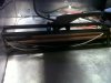
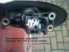
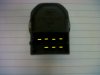
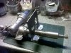
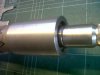
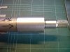
I been in grommet mode for the past few days, some hoses/lines were through panels without grommets, sigh, the rubber on some other grommets had dozed. I attach a before and after on the handbrake cables.

IMG01135-20130619-2050.jpg IMG01137-20130619-2111.jpg

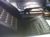
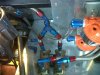
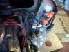
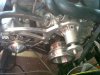
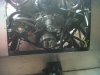
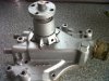
The fuel lines are presently taken run up from the tanks over the members of the chassis, I want to take these through the panel that the pumps are sitting on, you can see the 2 lines on the left of the pic below. I have the bulkhead fittings but no Fragola unions for the braided hoses,....:cry:

IMG01136-20130619-2107.jpg
 
With the central tunnel 'in bits' I'm considering moving the handbrake back by about 4" to 6". Perhaps (perhaps) in the future I'll put the gear lever on the centre tunnel in front of the brake lever. Has anyone done this, I read the IVA doc and there seems to be no restriction on the position of the lever, apart from being accessible and making sure it does not disengage when the button is not pushed. Below is the present position of the lever.

Welcome any advice others may have.
 

Attachments

  • IMG01139-20130619-2112.jpg
    IMG01139-20130619-2112.jpg
    160.7 KB · Views: 363
  • IMG01140-20130619-2113.jpg
    IMG01140-20130619-2113.jpg
    161.7 KB · Views: 385
Moved the handbrake back about 6" (150mm) to allow for a centre cable shifter in the future, had to shorten the link to the cables, all I need now is the money to buy a cable system :cry:.


IMG01140-20130619-2113.jpg IMG01139-20130619-2112.jpg IMG01148-20130622-1502.jpg IMG01151-20130622-1823.jpg IMG01153-20130622-1911.jpg IMG01155-20130622-1921.jpg IMG01157-20130622-1946.jpg IMG01158-20130622-2040.jpg
 
Wanted a day of rest from thumping and banging, so worked on how to get the mirrors mounted and importantly postioned on the door, without havng to drill holes in the door and iterate.
I want to use mini cooper mirrors, so bought a pair on ebay for £60. The general sequence is listed below:-
1) Made a Kelloggs 'hole template'.
2) transferred the hole to a bit of scrap ally.
3) formed and positioned the ally on the front clip overlapping the door and strapped it on with duck/gaffer tape.
4) lifted the clip and opened the door to allow the ally to sit in position where the door is or would be.
5) strapped the mirror to the ally and checked.
6) modified the hole to allow the mirror mount to be twisted and correctly positioned.
7) removed the mirror from the bracket and marked up the door, now all I need is courage to take a drill to the door.
I have also worked out the wiring for the mirror controls, I did have a full schematic but the colour coding only refers to looms and not the connectors of the mirror, I'll post this info separately.
I have not checked the field of view and whether these mirrors will get me past IVA, next step is to check visibility with some cones, poles, string and an old trigonometry book from A levels. The main purpose of the above was to see if I could develop a way top check all this without making holes in the car.

IMG01160-20130623-1657.jpg IMG01162-20130623-1657.jpg IMG01163-20130623-1658.jpg IMG01166-20130623-1701.jpg IMG01167-20130623-1704.jpg IMG01164-20130623-1701.jpg IMG01174-20130623-1743.jpg IMG01175-20130623-1744.jpg

Keith
 
Last edited:
Mini Cooper mirrors have a 3 pin connector, I have labelled them C, common, V, vertical control (motor) and H, horizontal control. Reversing the polarity of the voltage on the connections simply reverses the motor direction.
Driver's Side (right)
vertical control
C=+12V, V=0V, View DOWN.
C=0V, V=+12V, View UP.
Horizontal control
C=0V, H=+12V, View IN.
C=+12V, H=0V, View OUT.

Passenger's Side (left)
vertical control
C=+12V, V=0V, View DOWN.
C=0V, V=+12V, View UP.
Horizontal control
C=0V, H=+12V, View OUT.
C=+12V, H=0V, View IN.

Mirror internal connector wiring driver's side (right), Common (C) - Blue, V - Red, H - Green.
Mirror internal connector wiring passenger's side (left), Common (C) - Blue, V - Green, H - Red.
----------------
I want to use a Ford Focus control knob, simply because it is small, circular and kind of in keeping with the interior, oh and cost 99p, the postage was more. I now have to map the logic of the 7-way control knob to the above voltage logic,... wish me luck.


Keith
 

Attachments

  • Cooper-Mirror-Connector.jpg
    Cooper-Mirror-Connector.jpg
    227.8 KB · Views: 333
  • IMG01178-20130624-2010.jpg
    IMG01178-20130624-2010.jpg
    86.3 KB · Views: 331
  • IMG01177-20130624-2009.jpg
    IMG01177-20130624-2009.jpg
    95.5 KB · Views: 306
I attach the wiring for the Ford Puma (Fiesta) switch, I had previously mistakenly described it as Focus control knob. I have not tested this yet, but it looks like I can control the (BMW) Mini Cooper mirrors with a Ford Puma control knob. I'll bench test this weekend. K

Puma-Mirror-Switch.jpg
 
The above arrangement works, so a Ford Puma control knob can be easily mated to the Mini Cooper mirrors, I could do a video, it's not really that interesting. K
 
Nice info on the mirrors. I like the newer knobs out of the Focus, Fiesta, Mustang, etc. Very compact and unobtrusive!
 
Tidied up the hoses from the tanks to the filters, originally they weaved around chassis members, was not sure if the IVA inspector would be happy with this, so I put them through the ally panels with a couple of 90 degree bulkhead connectors. I used speedflow 101 range, as I could not easily get Fragola, which was used for the rest of the fuel system. Luckily I have a large and reasonably good pair of cable cutters; discovered that masking tape is better than PVC (electrical insulation) tape to stop the fraying, simply because it is fairly inflexible, if the ends fray at all, you will struggle to get the socket over the end, here's a before and after.
 

Attachments

  • IMG01136-20130619-2107.jpg
    IMG01136-20130619-2107.jpg
    204.4 KB · Views: 353
  • IMG01190-20130628-2027.jpg
    IMG01190-20130628-2027.jpg
    216.6 KB · Views: 369
Got the corsa C steering column back from the workshop, I had got them to make a bracket which will be welded to the chassis just behind the dash, as this bracket is functional, I kept the design very simple, it is quite a beast, 5mm steel, my worry now is, can I weld it to the chassis without blowing away the box section?

I show some pix of it simply taped to the column. I also got them to turn a collar for the top column bearing. When I got the column I removed the plastic and alloy casting from the top which had the steering lock, so needed to replace it with a simpler one. I may use another collar which fits over over this to allow me to attach an indicator stalk. My priority now is to get the bracket on the car so I can design the lower brackets and set the angles etc...
 

Attachments

  • IMG01201-20130704-2024.jpg
    IMG01201-20130704-2024.jpg
    176.7 KB · Views: 305
  • IMG01204-20130704-2204.jpg
    IMG01204-20130704-2204.jpg
    224.2 KB · Views: 319
  • IMG01202-20130704-2026.jpg
    IMG01202-20130704-2026.jpg
    167.4 KB · Views: 285
  • IMG01203-20130704-2026.jpg
    IMG01203-20130704-2026.jpg
    150.1 KB · Views: 271
Started back at the 40 today, first chance after my holidays. I've decided to fit an electric water pump in the front bay, to allow me to (a) get rid of the lump and (b) not to have to route the heater hoses down the centre of the car.

I have a couple of questions; I plan to remove the impellor from the pump but it still looks like the body of the pump will foul on the rear bulkhead, what would you advise, do I simply get this cut away?

Perhaps you can get a housing that replaces the pump and simply acts to split the water feed to the heads?

If I do retain the pump housing, what is the best way to block the heater ports on the pump, they seem to be pressed or screwed in?

You will notice the stat housing is not swaged, so will get the workshop to weld a bead round the edge to hold the hoses on.

K
 

Attachments

  • IMG01258-20130817-1303.jpg
    IMG01258-20130817-1303.jpg
    189.2 KB · Views: 295
  • IMG01259-20130817-1303.jpg
    IMG01259-20130817-1303.jpg
    173.1 KB · Views: 271
  • IMG01269-20130817-1625.jpg
    IMG01269-20130817-1625.jpg
    256.7 KB · Views: 275
  • IMG01268-20130817-1625.jpg
    IMG01268-20130817-1625.jpg
    266.9 KB · Views: 262
  • IMG01266-20130817-1548.jpg
    IMG01266-20130817-1548.jpg
    198.8 KB · Views: 277
Simplest least effort way to block them is to join the two with a section of hose with some solid bar in the middle of it. ie get a small length (30mm or so) of bar (stainless or aluminium) the same dia as the outlets. Get some hose with the same ID, push the bar into the middle and stick a pipe clamp round the middle. Then connect it to inlet and outlet with again suitable pipe clamps.
 
Thanks David, what I would like to do is clean up the whole arrangement, ideally close the unused ports and totally remove the impellor, shaft and bearing housing to flatten the front face, then perhaps press a disc into the hole when the bearing lump is removed? K
 
I cut the front off the pump, removed the impeller and shaft, and welded a plate over the top of the hole. I then removed the two hose connections, they are only press fitted in, and tapped the holes for a setscrew with rubber washer.

However, I have not run my engine yet. So have no idea if my plans are 'water tight' so to speak.
 
Jon, where did you cut? I have drawn 2 lines around the bearing housing, I am proposing to cut flush to the main body, so plan to cut at the lower line, below the lub holes, unless I'm told otherwise.
 

Attachments

  • IMG01270-20130818-1610.jpg
    IMG01270-20130818-1610.jpg
    234.5 KB · Views: 299
Jon's method is more work but is the next step up. Remove old tube, tap and stick set screws in. I'd use some dowty washers as well as some serious locktite (studlock or maybe even engineering adhesive) and some silicon sealant. They won't leak or move then! Can't really comment on the main shaft though.
 
Brett thanks this is the pic I need for the guys in the workshop. I knew I had see a pic somewhere, boy could I find it, and in the end had actually sent a PM to Brian.

I had sent you a PM re riveter, did you get it?
 
Yes, sometimes being a long time member here and having an okay memory helps :)

I did, but I had already answered the question in the thread you referenced a while back. I'll PM you the answer
 
Back
Top