
You are using an out of date browser. It may not display this or other websites correctly.
You should upgrade or use an alternative browser.
You should upgrade or use an alternative browser.
Custom transaxle
- Thread starter leonmac
- Start date
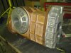
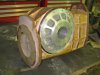
Did a couple of hrs in the work shop today working out selector positions and fitting the reverse idler shaft and gears. I'm now at a crossroad, Casting the diff housing is a given but I'm now thinking for fabricating the gear case. the plan is to laser cut the end plates that hold the bearings then using tube cut to precise length and studs that will sandwich the end plates and then fill in the casing flat plate. My thinking is that the end plates and studs do all the work and the side's main purpose is to hold the oil in. That is a very simplistic view and obviously the side's as such also provide a great deal of the strength. The other option is to continue with the mould and cast the main case. anyway I have taken some photos and hope you can get a rough idea as to where I'm heading. Cheers Leon.
Attached Thumbnails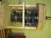
Cast the gearcase Lion.
You have a handle on the pattern making.
You will get pin holes from fabricating it and that will bring annoying oil leaks.
Plus it is a prototype if changes are needed it will burn you to have to fab a new unit instead of casting and machining.
Welding all those components in different directions has got to cause twist in places you dont want.
I love this thread, big commitment required.
Well done on the first casting, its like being a dad.
Jim
Last edited:
+1 on that, keep plenty of beef in the castings. The shunting forces helical gears put on the end casings should never be under estimated, a lot of gearbox failures are to do with the lack of rigidity in the casings rather than the gears. G50 side cover is a good example. How were you going to extend the input shaft??
Bob
Bob
With the 2 shaft configuration I will be driving through the lay shaft so I have a couple of choices 1) make a complete shaft with the Chevy/ford clutch spline one end and then spline the other end in much the same way the Hewland shaft is then cut the gears off the existing lay shaft and internally spline them 2) spline the bearing surface of the existing lay shaft then use a Winters coupler to join it to a custom made input shaft. 2 is easiest but my concern is whether there is enough meat in the bearing end as it's only 20mm long but it is 30mm diameter. Cheers Leon
The last time I had a play with shafts like this I had an input shaft extended and beam welded. It was something new to me at the time and I must admit I was apprehensive but after machining and hardening you would never have known it was an extended shaft. just thoughts.
Bob
Bob
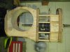
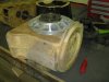
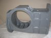
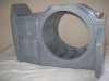
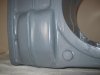
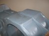
Hello Guys, it been quite some time since I last posted but I have been toiling away on this main case mould so thought I'd put up some pic's of what I have so far. I have painted it with a sanding filler so once it is hard will sand it with some fine grit paper to get a nice finish then paint it with a 2 pack paint for durability. I have to talk to the foundry as to how they want to cast it. There is a bulge on the right side for the reverse idler so it makes it just that little bit harder. The company I use do the Cases for Hollinger and Other after market company's so I'm sure this will not be a challenge for them. You may note that the rear casting stands up above the rear case, this where the shift rod will come out and be facing forward. This makes the gear shift very simple as it will just be a single rod that moves back and forth and turns the same as a Hewland, I have already figured out how the forks etc will work and now just need to get this cast so I can mount the guts in it.
cheers Leon
cheers Leon
Last edited:
Hey John, Does the LS block have the same B/H pattern as the earlier Chevy blocks. If so then my B/H will work as well, it's the same as a Lola T332. I still have a lot of work to get to the finished item The good thing is, I have it all planned out just need the time and Money to complete it. Have you got another build on the drawing board?? stay in touch mate, cheers Leon
The bellhousing pattern is the same on the LS and earlier small block engines except that one hole is not used on the LS. The big difference between the engines is the crankshaft. It uses a different bolt pattern and the crank does not stick out from the block as much on the LS as it does the earlier small block.
Jim Rosenthal
Supporter
I still don't understand why you want a wooden transmission. ")
I still don't understand why you want a wooden transmission.
Hey Jimbo, I'm the smartass on this forum, back off :furious:
Treemendous trans :thumbsup:
Bob
Terry Oxandale
Skinny Man
Hey Jimbo, I'm the smartass on this forum, back off :furious:
Even I saw that coming!
Have you got another build on the drawing board?? stay in touch mate, cheers Leon
lets just say the dream might just get realised, will know by tomorrow, either way I will be in for one when its a goer.
cheers John
What's wrong with wood ?? its a renewable resource, its easy to work with, it has no thermal problems ( except fire) its light weight, give it good coat of 2 pack and its even quite strong. I think you guys are just not seeing its true potential. but just to put your minds at rest I will magically turn it into Aluminium as I did with those other parts at some point soon. Cheers Leon.
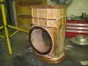
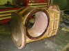
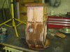
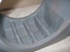
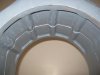
I have spent several hours sorting out the Reverse idler shift mechanism and now have it done. I now need to do the forward gear shift rods which I have already figured how they will work just need to make the ends that the main shift rod will activate on. After talking to the foundry guys I am going to now split the pattern through the middle and make it like a split case although it will be cast as one piece. This means I can make the core inside the pattern and not have to make core box's also this allows me to make the diff section lighter by hollowing it out which would be impossible if the pattern was left in one piece. I will post photos of the split case once I have finished it ready to send to the foundry. cheers Leon
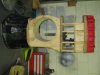
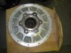
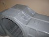
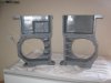
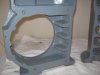
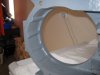
More time spent on the T/A pattern, I had it split down the middle by a local mill that has a huge band saw I put it in a frame so it could be held properly and run through true and square. I then hollowed out the diff section leaving ribs top and bottom, these line up with the studs that will hold the side plates and give strength and stop flex in the sides, I then put bosses in where oil will be pumped in and extracted from with the pump that will be driven off the lay shaft at the back, one will spray onto the crown wheel as it rotates away from the pinion so as not to create hydraulic pitting and one will spray onto the main gear stack it will sucked from the diff section though a boss at the bottom R/H side at the rear. There is still some matching up inside the housing to finish but it is almost there. Some photo's to look at, Cheers Leon :thumbsup:
Attachments
-
 Gear Box Pattern 06.jpg82.3 KB · Views: 727
 -
 Gear Box Pattern 07.jpg81 KB · Views: 512
 -
 Gear Box Pattern 08.jpg103.7 KB · Views: 514
 -
 Gear Box Pattern 09.jpg86 KB · Views: 505
 -
 Gear Box Pattern 10.jpg107.9 KB · Views: 534
 -
 Gear Box Pattern 11.jpg102.7 KB · Views: 482
 -
 Gear Box Pattern 12.jpg87.7 KB · Views: 454
 -
 Gear Box Pattern 13.jpg96.5 KB · Views: 676
 -
 Gear Box Pattern 14.jpg105.6 KB · Views: 490
 -
 Gear Box Pattern 16.jpg94.8 KB · Views: 488
Last edited:
What's wrong with wood ?? its a renewable resource, its easy to work with, it has no thermal problems ( except fire) its light weight, give it good coat of 2 pack and its even quite strong. I think you guys are just not seeing its true potential. but just to put your minds at rest I will magically turn it into Aluminium as I did with those other parts at some point soon. Cheers Leon.
Nothing wrong with wood Leon:thumbsup: I have used all sorts when mold making ,as long as it holds up to the pounding they will give it at the foundry it's good enough.
Bob
Similar threads
- Replies
- 0
- Views
- 257
- Replies
- 5
- Views
- 721
- Replies
- 3
- Views
- 1K
- Replies
- 4
- Views
- 2K
- Replies
- 1
- Views
- 268