Joel K
Supporter
Dusty,
Your build is looking good.
With regard to the intake, a few ideas...
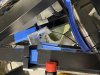
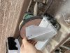
1)How much room do you have between the wall and the throttle body? I have a 4” Cobrahead silicone intake tube that may work. It needs about 2” of clearance.
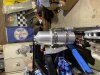
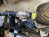
2)Most feeding a supercharger cut away a piece of the frame and weld in support. Then run a 120 degree 4” elbow to the throttle body.
3)ITB setup
4)Also, a high mount intake like Mark B is running places the intake tube the way you want..
Your build is looking good.
With regard to the intake, a few ideas...
1)How much room do you have between the wall and the throttle body? I have a 4” Cobrahead silicone intake tube that may work. It needs about 2” of clearance.
2)Most feeding a supercharger cut away a piece of the frame and weld in support. Then run a 120 degree 4” elbow to the throttle body.
3)ITB setup
4)Also, a high mount intake like Mark B is running places the intake tube the way you want..
Mark B's Build Thread
I asked after this post came up and was told Olds Aurora but not what specific model year...
www.gt40s.com
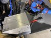
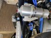
") I did have to customize (cut/weld) the intake lid, though, to add the elbow. I have a bunch of pics and happy to share more info if you need -- feel free to IM me.
I did have to customize (cut/weld) the intake lid, though, to add the elbow. I have a bunch of pics and happy to share more info if you need -- feel free to IM me.