Jason's Coyote Powered RCR40 Downunder

Jason, I was sitting in a chassis (DRB) being modified for a tall person, and in addition to extending the footwell the steering rack had been rotated in similar fashion. Required quite a bit of work for the new mountings, but kicked the steering column up higher to still be above the driver's feet in the new (extended) pedal box position. I believe it is important also to not get too much of an angle in the steering column universal joint(s), as you will lose linearity (they are not CV joints).
 
Next job was to check the steering column geometry. I spoke to a very helpful engineer that works on OE steering systems and quickly learnt that column geometry and design is a science, what a surprise! Ensuring correct steering feel by controlling shaft angle deviations and shaft relative velocities with correct joint phasing and phase valley centre positioning is critical, holy crap!

Using a proprietary software program all the correct steering angles and phasing was calculated. Angling the rack was the best thing I could do as this provided a good setup where the steering column angle was very close to the rack angle. With almost equal angles my steering was reported to be better than most OE setups so I was very happy with the little joint phasing required.

phasing.jpg


Now to mount the column.

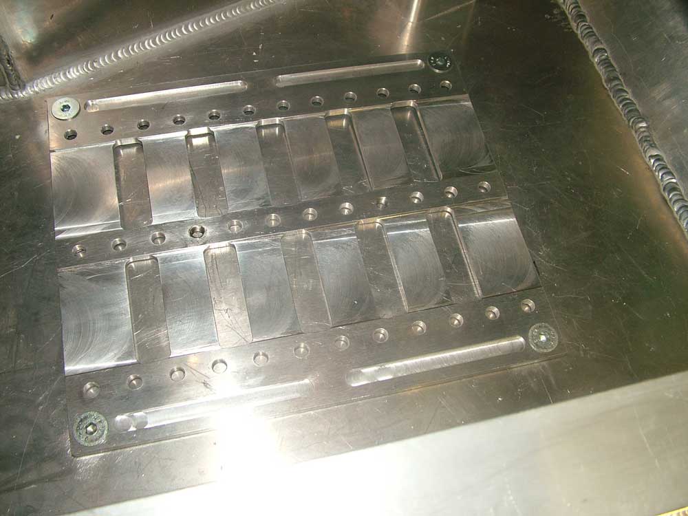
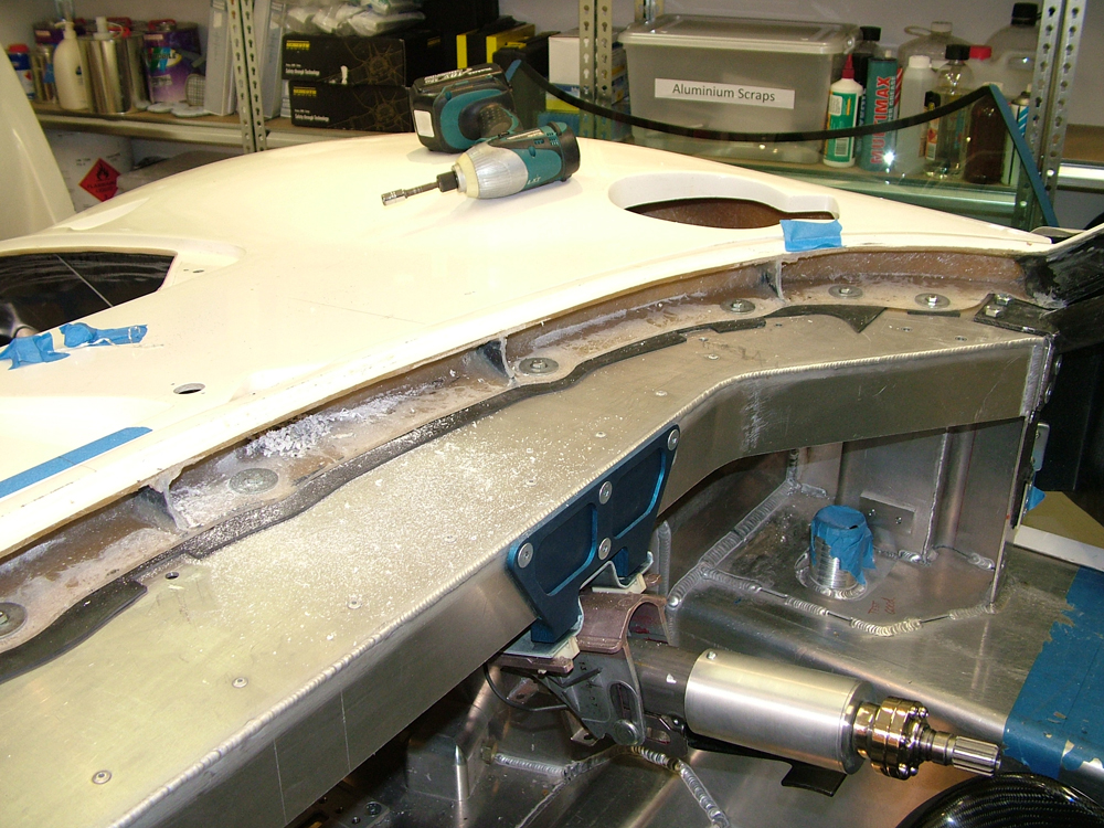
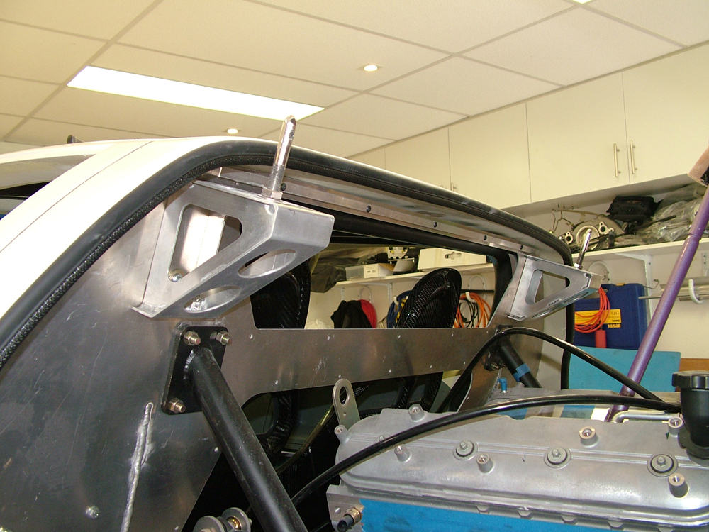
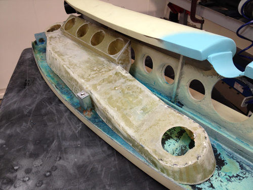
I designed a bracket to mount the column at the optimum angle. As the column is adjustable I simply ensured I could get full range of motion as I have not yet decided on a seat. The brackets were designed to hold the OE column mounting plate and also strengthen up the RCR dash cross member which can flex before the column is fitted. Tying the front of the dash to the chassis via the OE sheet metal structure has resulted in a VERY rigid mount.

DSCF5436.jpg


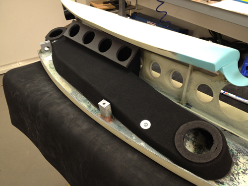
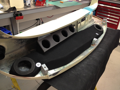
Below: Mounts in place, you can see the small rear ones I also machined up. A cut was made between these to clear the column. The bracing affect of this very rigid OE structure more than accounts for this material removal.

DSCF5454.jpg


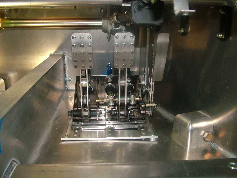
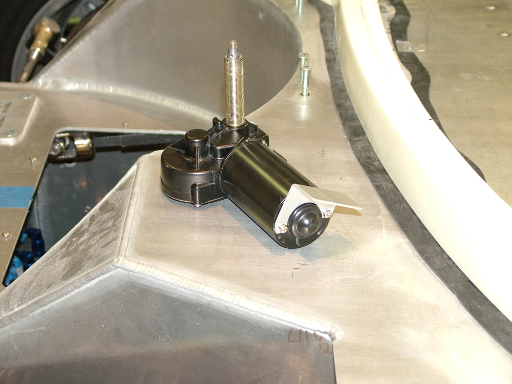
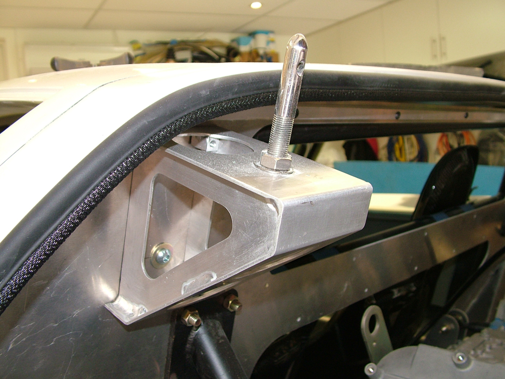
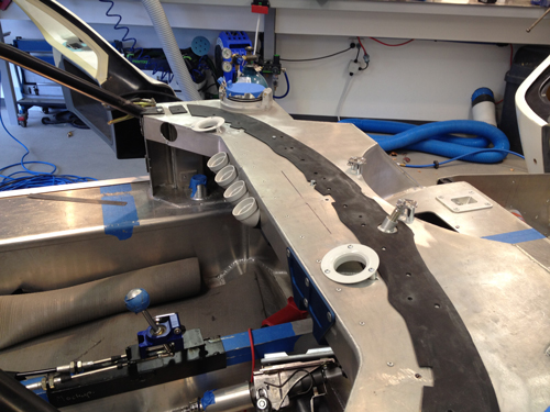
Below: Column fitted. The ignition key will be on the dash or centre console and the ADR requirement for a anti theft lock device will be fitted to the transmission as permitted in the ADR's. I did not want a bulky column in the car as it just looks out of character.

DSCF5465.jpg


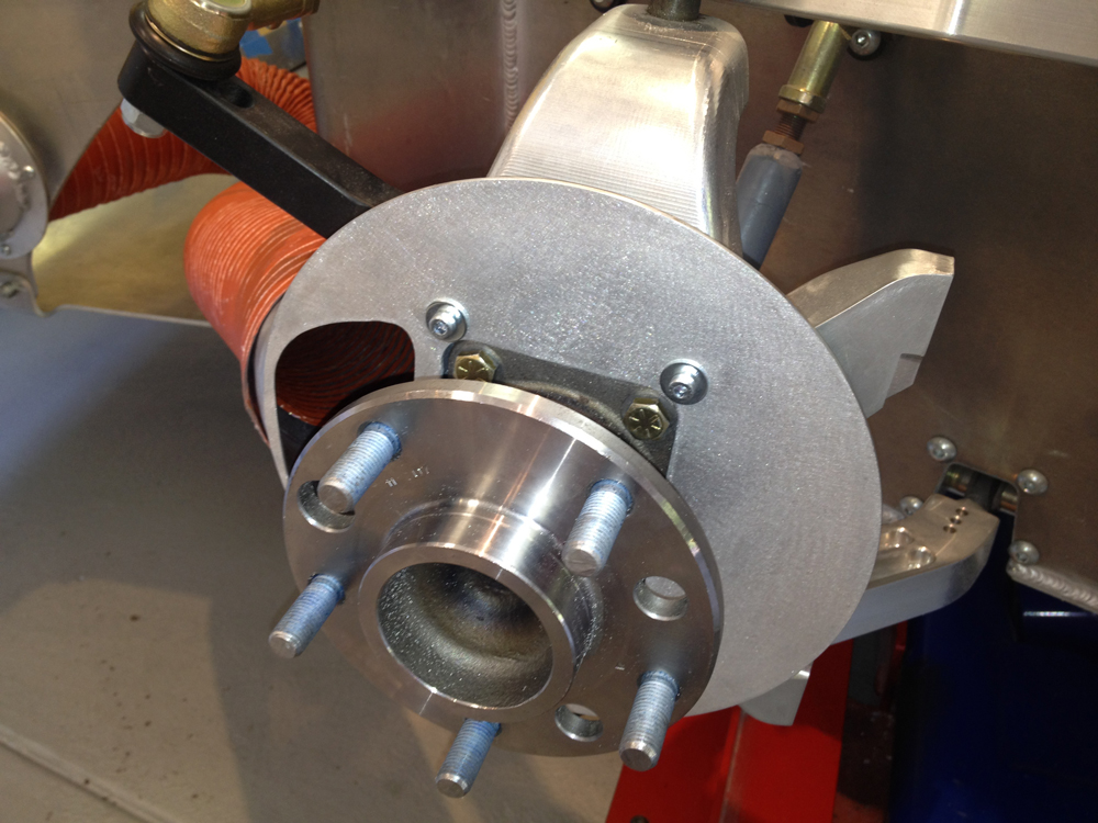
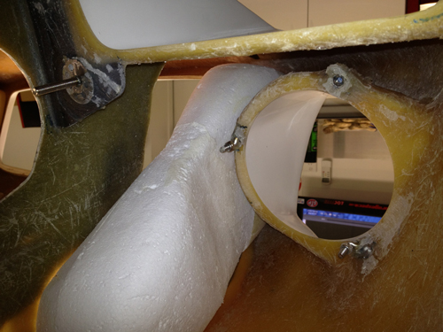
The column fits very close to the top of the foot well. All that is left to do is get the shaft welded by a certified company (need to find one in VIC Australia). You can see the splined alloy OE collapsible section of the column. I also have a second telescoping section near the rack to allow for the rake adjustment of the column and add additional intrusion protection.

DSCF5471.jpg


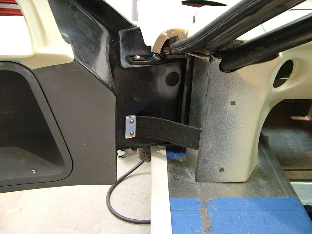
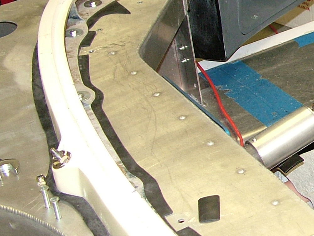
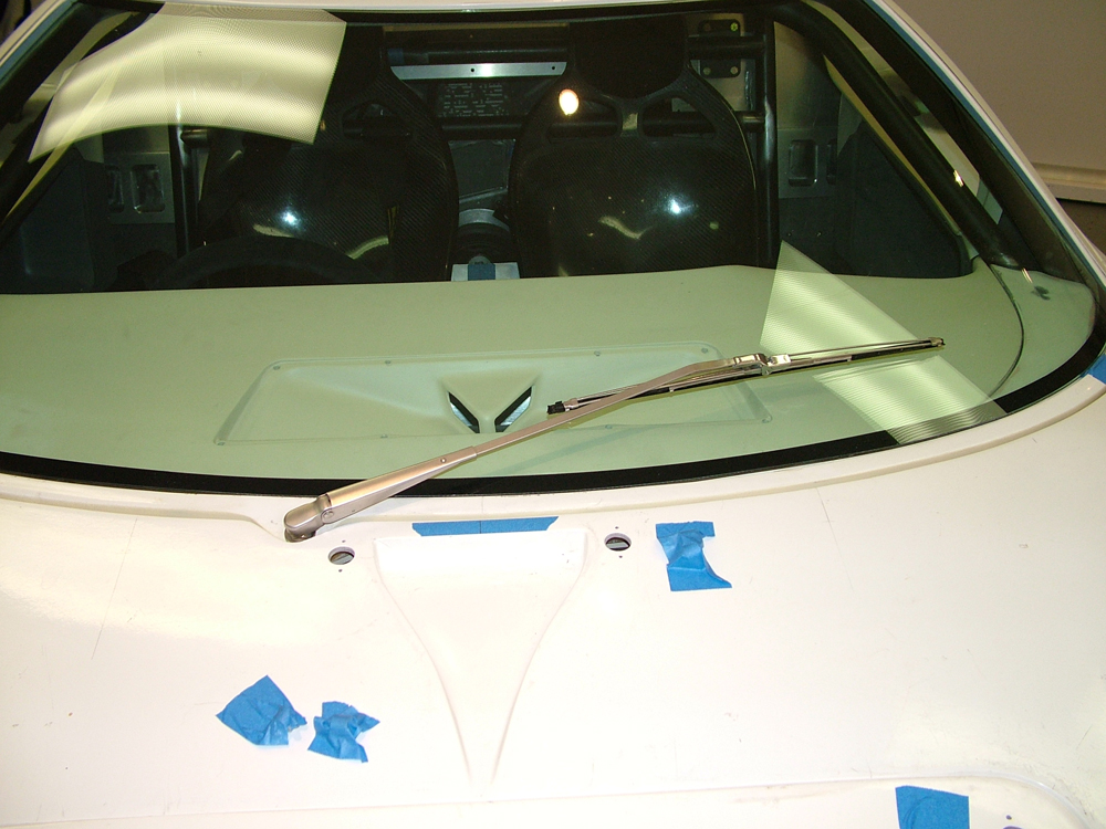
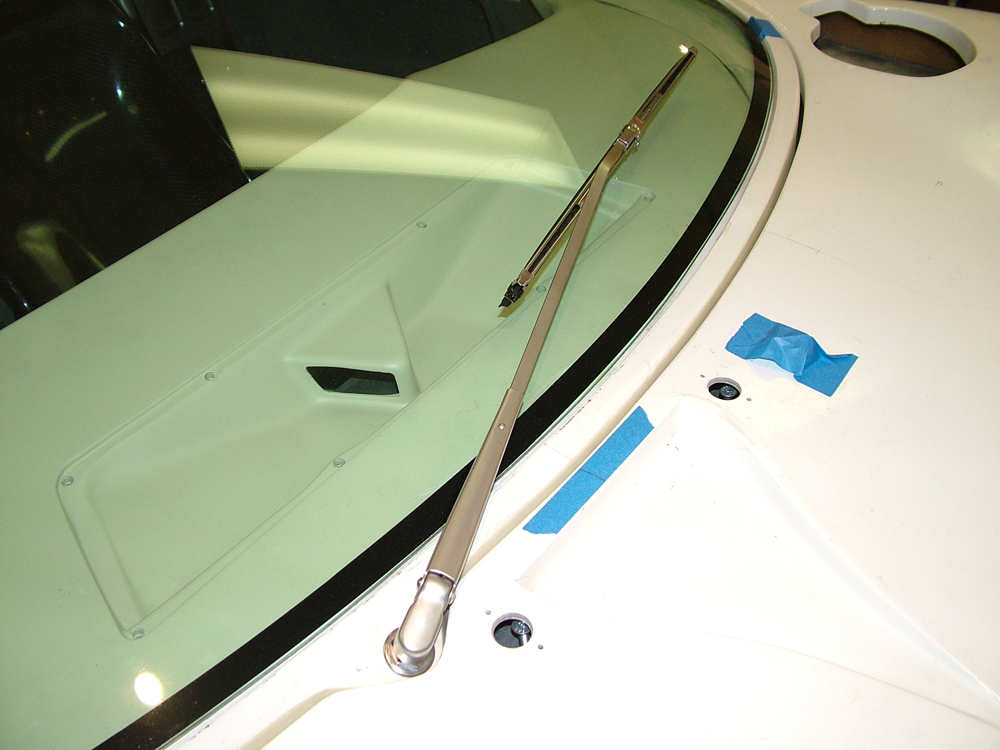
The steering angle sensor (black thing near the first joint) and some of the redundant brackets may also be removed later depending on the column dressing fitted. All in all the steering now looks very neat, will be compliant and offers full adjustability. A small clean up around the dash (blue below) was all that was needed.

DSCF5485.jpg


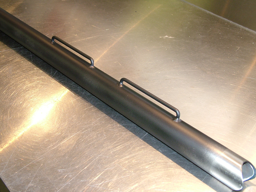
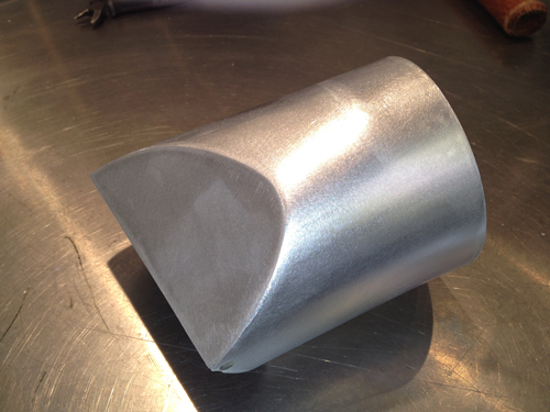
Adjustability is great. With the rake and reach adjustment available removing the wheel could possibly be be avoided. A final bit of glass work aroung the column cleaned up the dash (layed glass on a Coke can to get the shape!).


DSCF5478.jpg
DSCF5479.jpg


This took a lot of time but was important to me to get right. I have seen the fully compliant adjustable RF steering system and was most impressed, so they set a high bar for me to aim for. An OE Ford steering wheel fits perfectly for compliance measures as well. I have purchased a 14" Mota Lita so now I need to try to mount that one day in the far far future!
 
Last edited:
Hi there jason,Just starting out on a gt 40 build myself whith a buddy,live in Melbourne too.We have just bought an unfinished rolling chassis and body, set of body moulds ,chassis gig and a pile of patterns and other parts.So the journey begins.I am a fiberglasser by trade and run a small fibreglassing buisness in Melbourne.My buddy is sructural steel fabricator who runs his own business.Have shed and try to play out there often.Got a metal lathe and some other toys that will come in handy for the build.May be able to swap notes on stuff.Regards Conrad:shy:
 

Chuck

Supporter
Jason:

Beautiful work. Nothing more irritating than a steering column that rattles in your hands. That looks solid as a rock. Very impressive.
 

Randy V

Moderator-Admin
Staff member
Admin
Lifetime Supporter
Jason:

Beautiful work. Nothing more irritating than a steering column that rattles in your hands. That looks solid as a rock. Very impressive.

X2 on that - Exceptional job! :thumbsup:
 
I don't know why it took me this long to see this thread, but better late than never. Jason, your craftsmanship on this project is outstanding. Having the skills for CAD, machine work, fiber-glassing, etc. are definitely a plus. I look forward to the continuing saga.
 
Making the Wheel Boss and Column Adaptor Boss

With the desire to be able to fit an OE steering wheel for compliance I needed to manufacture a boss to adapt the Sparco quick release and fit the Moto Lita wheel. With many various bolt PCDs between Sparco and Moto Lita it was a bit of work!

GT40Wheel2.jpg


The alloy cover added to the column will be anodised black.

DSCF5733.jpg


I will be manufacturing a cover for under the column to hide all the sharp edges from legs. I would also like to add one indicator stalk somehow.

GT40Wheel4.jpg


Anyhow now done, just need to get all the alloy parts anodised flat silver and the metal parts plated. Also thanks to DRB for the Ford GT badge, diameter is a good size for this Moto Lita Wheel.

One question, I have 55mm between the back of the wheel to the top edge of the dash, Are others setting the wheels closer to the dash than this? I can adjust the wheel closer as its adjustable but this is as far away from the driver that it will go.
 
Bit of a delay since the last post but I have been moving slowly.

Being tall and not wanting gurney bubbles has meant that to wear a helmet on the track two sets of seats will be required. A set of trimmed authentic 40 leather seats and a set of bare bone jarring carbon ones. I fitted studs to the floor in the same positions to fit both seats. The carbon ones below worked out really well. With the base of them 3mm from the alloy floor I have good head room.

DSCF5840.jpg


DSCF5830.jpg


I have also fitted the crutch and hip Schroth belt sets. What a job to do correctly, I see why Tom spent so long organising his!! Just need to plan the shoulder belts now and will have to employ some outside help. I have also fitted frames for the padded leather grommet seats to check for space and alignment, these now need to go to the trimmer.

DSCF5749.jpg


The shifter support shown is only a mock-up but the shift cables are connected to the transmission and working.
Also completed the door striker support in billet aluminium. Designed to carry load to the cage. It has a hidden fixing to the cage to hold it in position if it is under load due to a side impact.

DSCF5829.jpg


Also fixed the pedals to the floor. I designed and manufactured a billet pedal support that allows 6 positions and also ensures the pedals are level in the vehicle. The floor is warped during welding and this ensures the pedals are not warped and bind when bolted to the floor.

DSCF5633.jpg


DSCF5636.jpg


Also fitted a leather door strap from Roaring Forties to the car which I like as its simple, comes with all the fasteners and easy to fit.

DSCF5843.jpg
 
Yep been a while, but I have done a few things.

Decided to fit the Schroth 6-point belts. Fair bit of work to get the mounts in and meet the Schroth installation guidelines but got it done. Also decided to use another bar like Tom to attach the shoulder belts properly. Welded on stays to stop the belts moving out of position.

DSCF6121.jpg


belts.jpg
 
Decided to tackle the lights. Made up adjusters etc for the headlights and it has worked very well. get behind the lights and I have 3 knurled adjusters to aim the headlights. Parts with holes shown are glassed into the body.

DSCF6162.jpg


DSCF6165.jpg


For the driving lights I used Narva light enclosures to hold the Hella 5.75" lights. They allow full adjustment and come with a chrome bezel that looks great.

DSCF6154.jpg


DSCF6156.jpg


DSCF6155.jpg


After fitment it all looks great. Still need some indicators.

DSCF6168.jpg


Then I started on the wipers. I really did not like the cable drive wipers. Too much work and too many parts. Used a direct drive geared wiper motor. Has auto park etc, great unit. Made up some brackets and a special adaptor at the end for the wiper arm I'm using and it fitted great.

DSCF6145.jpg


In the image below you can also see my reversal of the spider fitting system. I did not like the screws all around the front of the spider, so I reversed and reinforced the lip under the spider and fasten under the dash. My dash comes out with minimal fasteners so I preferred this. The seal will be trimmed later.

DSCF6150.jpg


DSCF6136.jpg


The wiper arm is a NOS 1985 Mercedes 380SL stainless steel arm mated to a Ford GT wiper blade which closely resembles the originals. I think most arms were black so I will most likely powder coat it later.

DSCF6171.jpg


DSCF6173.jpg
 
What seats are you using? They look like Tillett's, but the headrests aren't labeled, and I can't seem to match them with anything in their catalog?
 
Zoey, seats are full carbon custom made locally.

I also made some alloy rear clip stays.

Do not want the rear clip flying up so I made some rear clip brackets. Got to keep practicing tig welding the aluminium so I was happy with the result.

DSCF5786.jpg


DSCF5783.jpg
 
Brake Cooling Ducts

After seeing some great brake setups on a Roaring Forties GT40 I felt I should cool my front brakes as well. Looking at empty front ducts would annoy me so there was that reason too. First step was to make an alloy plate to get the air into the centre of the rotor.

IMG_11712.jpg


IMG_1171.jpg


A bit more alloy bashing and welding and it was looking OK. Getting the alloy tube to transition and hold shape at the hose end was tricky. I knew it had to be secure to withstand the load suspension movements may place on it.

IMG_1188.jpg


IMG_1183.jpg


IMG_1191.jpg


There is a close clearance to the rotor so the air is fed well into the rotor and will exit out of the cooling vanes. Next job was to get the air through the front of the chassis plate. I made another alloy to be and bolted it into the chassis.

IMG_1198.jpg


The seal is a temp one, it will be cut properly and glued later. As the clip closes the duct in the body will seal to this as it has a taper cut.
Next job was the fibre glass duct. It needs to be a complex shape to get to the position I want it to smoothly. I also did not want to look in the front of the duct from outside the car and see fibre glass texture so I made a foam pattern that fits inside the body.

IMG_1212.jpg


IMG_1216.jpg


I covered the foam in tape and mould release. Then covered it in fibre glass, split it, finished the inside and rejoined them. Now when you look in the front of the vehicle you will see a perfect smooth duct up into the body.

IMG_1220.jpg


All in all it came out pretty good. Next job is to fix the ducts inside the body.
 
Condensor Radiator Fan Module (CRFM)

I decided to over cool my engine and design a larger radiator than the stock RCR unit. There is nothing wrong at all with the RCR unit, I just really wanted to fill the available under bonnet area. I will also be using a large AC condenser so I wanted to account for its impact on the radiator. I designed the following unit for manufacture:


RAD-DRG.jpg


RAD-IMG1.jpg

RAD-IMG2.jpg


Core face area is much larger. I also wanted to accommodate higher power 12"fan units (each delivers 1565 CFM at 0" static). These large 318mm diameter fans will cover the maximum core face.
The resulting radiator is quite a size jump over the standard unit as can be seen below.

RAD-IMG3.jpg


IMG_1633.jpg


IMG_1632.jpg


It also fills the entire frontal area available compared to the stock unit.

RAD-IMG5.jpg


RAD-IMG6.jpg


I am very happy with the result but it was a lot of work!

IMG_1653.jpg


IMG_1659.jpg


Looks a little like a truck radiator now though!

Next job the underdash AC unit and ducting. Going to make that custom as well.
 
AC Unit

I decided to make a custom AC unit so that I could tuck it up and out of the way. To do this I purchased a good SPAL blower motor and evaporator case and begun to make a fiberglass transition duct. This allowed the blower to sit up in a triangular portion of the passenger side of the under dash structure.

IMG_1524.jpg


IMG_1525.jpg


The temporary "sticks" aligned the blower and evaporator so that they fit under the dash perfectly. I then constructed a fiberglass duct around them.

IMG_1531.jpg


IMG_1537.jpg


IMG_1534.jpg


IMG_1538.jpg


IMG_1674.jpg


IMG_1678.jpg


I then constructed a plenum chamber for the evaporator to blow into and distribute the air to the side vents and center dash outlet. Covered in foam to insulate the duct it has angled foam outlet faces that seal to the chassis to direct the air to the vents.

IMG_1619.jpg


IMG_1679.jpg


IMG_1682.jpg


The duct lines up with the chassis points shown below. The air comes out of the evaporator, into the plenum duct, out of the center duct or down into the chassis through ducts to the LH & RH vent outlets. In this way dash removal takes only 3 bolts and the eventual harness connection. No duct connections are required and the AC unit is not disturbed.

IMG_1579.jpg
 
Jason, love your work.
I like you A/C, dash and spider solutions to a better built mouse trap.

RCR work is to notch, but you are making there design even better with your own added touches of design.

Great job.
 

Randy V

Moderator-Admin
Staff member
Admin
Lifetime Supporter
Wow Jason... Very nice work! You've managed to address a number of very challenging areas in building your RCR..
 
Back
Top