Fabulous! What a great project.
Dave
Dave

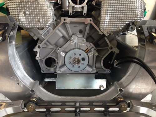
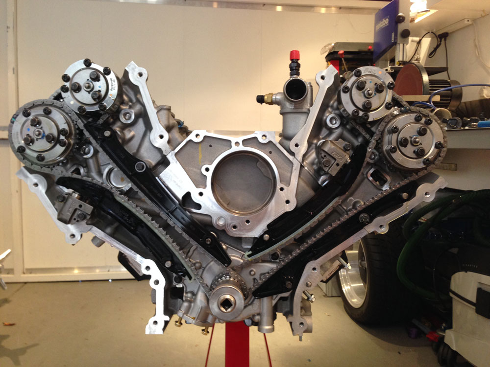
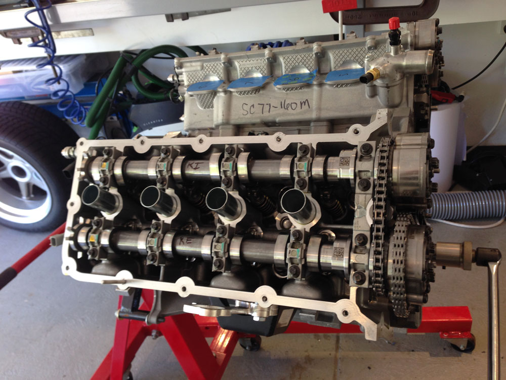
Coyote Engine
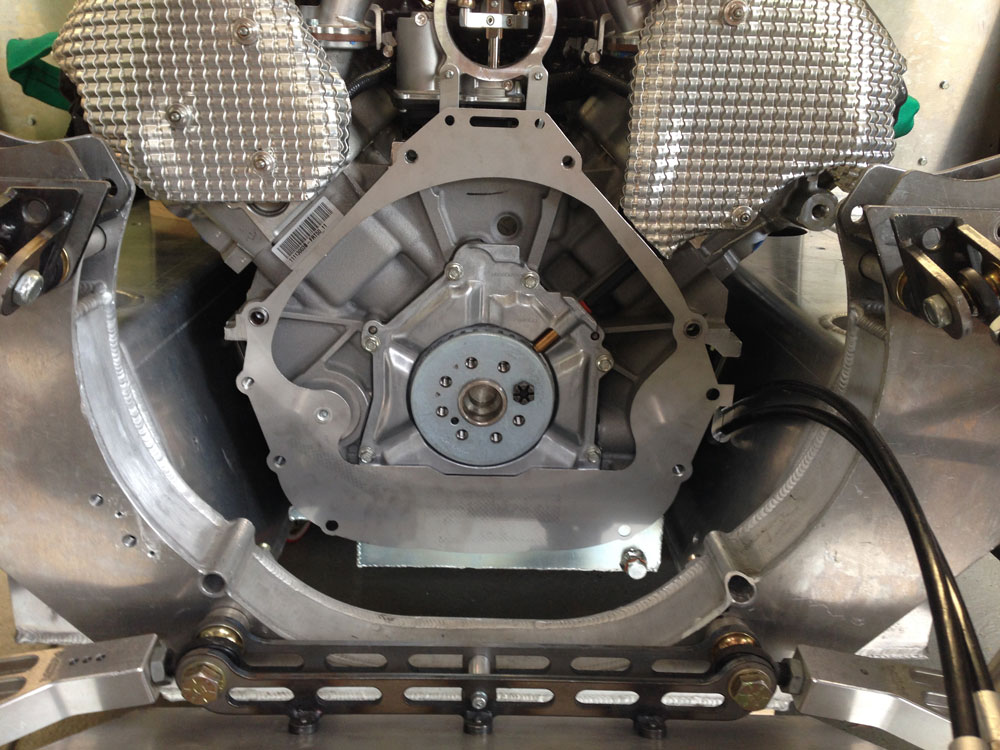
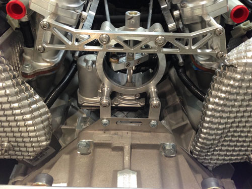
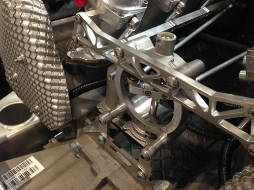
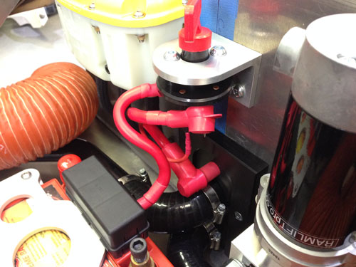
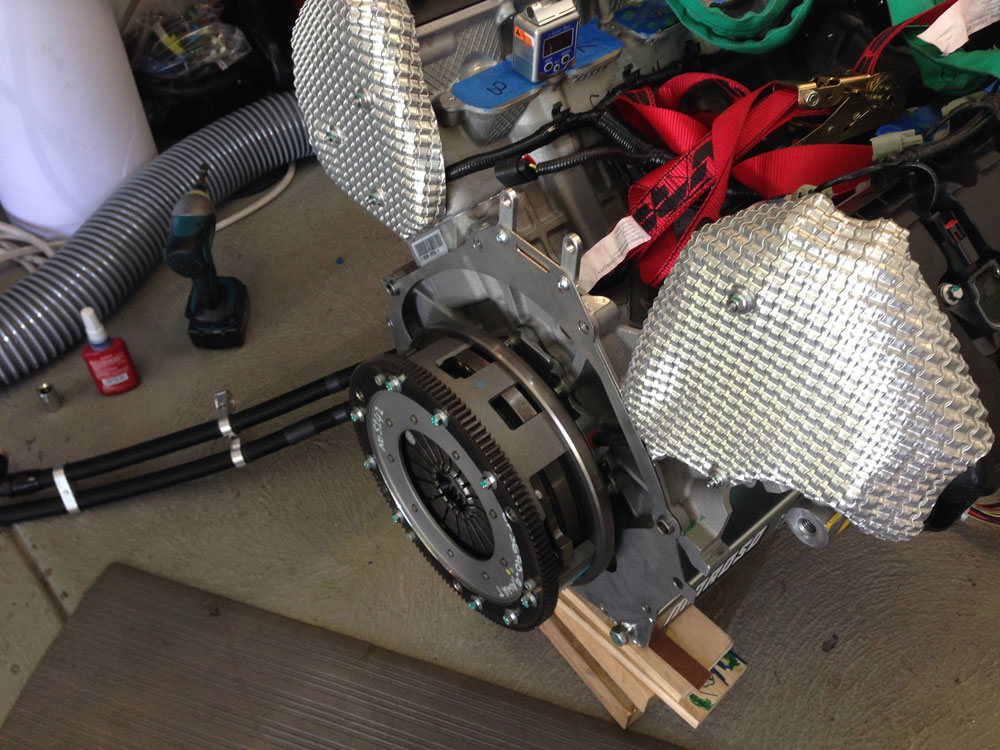
I designed and manufactured a full custom serpentine layout to fit the ford alternator in the engine valley and a small but capable AC compressor in the tight engine bay without cutting into the RCR chassis. Big job as I had never built one before. Thanks to Roaring Forties for some guidance in this area especially with the alternator placement suggestion. pully gauge lines are spot on and getting the right length belt only took three goes to get it perfect!
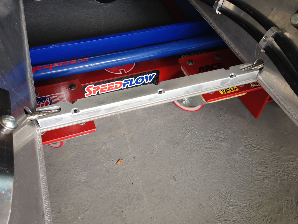
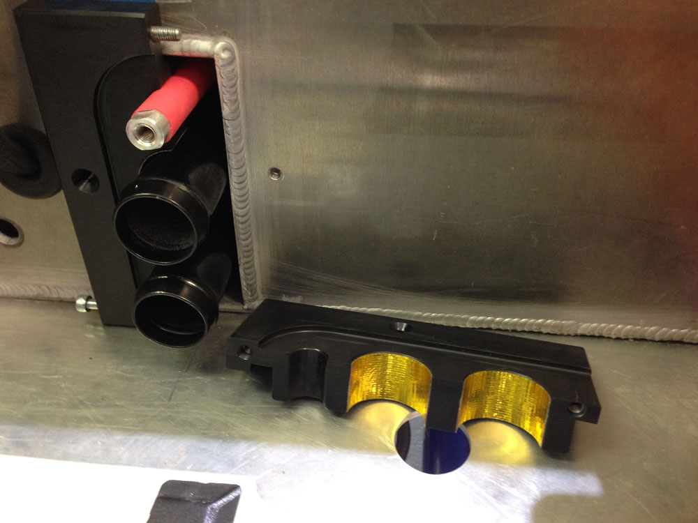
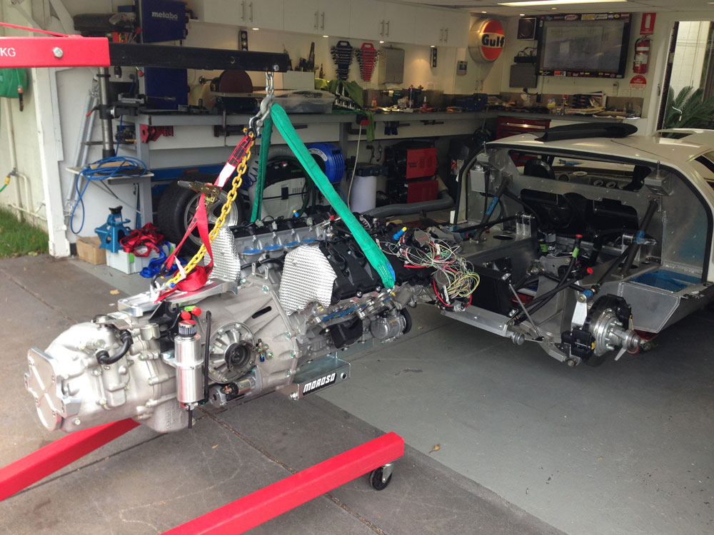
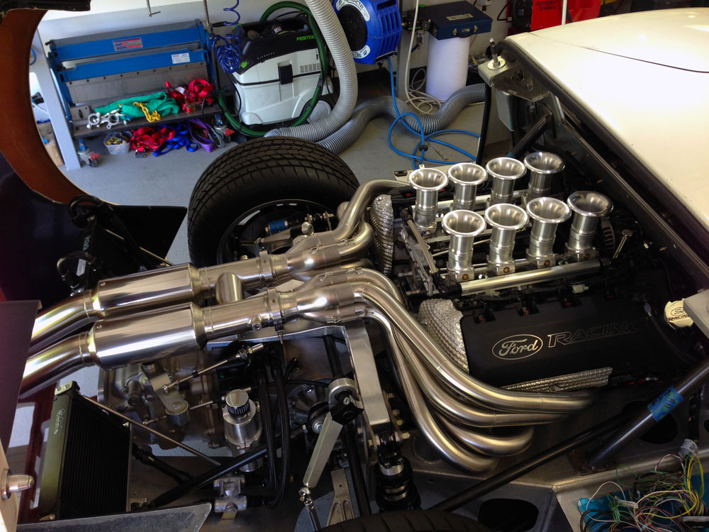
At the front you can see the nylon blocks that hold the tubes securely. The red alloy bar that runs the length of the car is the way I get power from the battery to the alternator and starter. Much lighter and simpler than a copper cable (lower alloy electrical conductivity allowed for).
![rad[1].JPG](http://www.gt40supercharged.com/gt40_images/rad[1].JPG)
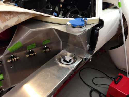
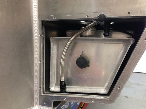
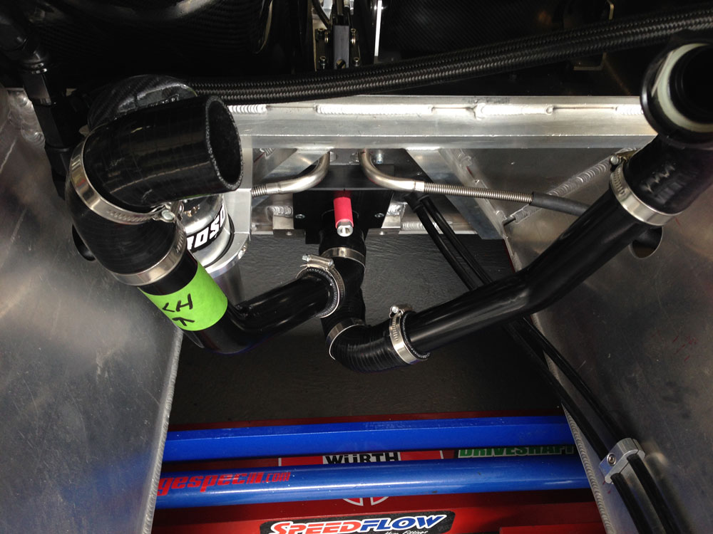
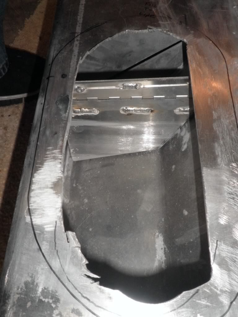
Can anyone tell me if a coolant "vapor" or "bleed" line is mandatory from the top of the radiator to the rear overflow bottle? I can do it but its a long line from front to back. If the lack of it means I need to bleed when first filling the system I could deal with that. See the line I am referring to below:
Any suggestions appreciated.