M20 Dreaming

Hi Leon,

your chassis is looking really good

Myself, and Im sure many others look forward to your posts. Your project is extreemly intresting

I cant wait to see some more pics

Mick
 
Leon
I have some good pictures of an M8F if thats any help, love your work and will get to see it some day.
Cheers
Russell
Had my entry to the Ron Roycroft meeting returned as my car is representitive of a 1973 `Gemco` and their cut off was 1969...so have now reminded them that its in fact a rendition of a 1969 Mclaren..now we will see what go`s. I would love to get a run there.
 

Attachments

  • l-30.jpg
    l-30.jpg
    760 KB · Views: 591
  • l-34.jpg
    l-34.jpg
    725.8 KB · Views: 558
Hi Guys, I'm at work now for a month so won't have any progress to report. Terry, the photos don't show it but there is plenty of room between the top link and the spring platform. Russell, thanks for the photos, they will help with the bottom shock mount. Andrew sent me a heap of photos he had and every thing helps so I appreciate it. I feel like I'm on the down hill now with the front end starting to get close to completion although I know its the little detail bits that take the time to do and get right. Thanks for everyones encouragement. Cheers Leon.
 
Hey there Terry, next month has been and gone with a little progress, I got a steering rack and started fitting it in the tub, Man its tight in there, so I have had to mod the pedals to give a bit more space for feet. I made some neat brackets to hold the ends of the rack and they will also stiffen up the rear/lower "A" arm mounts. I also did a bit more on the wheel and Bellhousing Moulds. Unfortunately I was called back to work a week early and given very little notice (They rang 8pm I was flying by 10.30am) so no Pics. will have to wait another month to get home and get the steering finished.
Sorry Russell. Never got a chance to drop you a line, will do it next time home. I was up at Torbay last week to by a Jeep, is that close to your place?? I was on a clock so didn't have time to visit, went from New Plymouth to Torbay got Jeep and back to NP in the same day 850kms so we were not mucking about. Cheers Leon.
 

Terry Oxandale

Skinny Man
I'm patient. Work has me out of town more than in town, then I went to the INDY 500, and probably won't get to put in more than 3 or 4 hours per week on my project for a while. Aside from the B2's low flyby over the field during the National Anthem (truly an emotional moment), the Lotus was the next best sight (sans the many beautiful and drunk women chasing after the money). On the track, this car was just gorgeous!
 

Attachments

  • Jim Clark Lotus from INDY.jpg
    Jim Clark Lotus from INDY.jpg
    64.1 KB · Views: 345
Last edited:
Hello guys, long time since I posted any progress on the M20, I have been busy with other things and short hitch's at home. I bought a Jeep afew months back so have been doing some mods to it but have managed to scrape a few hours together and mounted the steering rack. This has created some problems with my pedals and now I have to redesign them. The bottom line is there is so little room in the foot well that I need to push the pedals forward to get my feet in there and work everything with out it being like the "Small Tyre Shadow". I made some brackets that not only hold the rack but also help stiffen the bottom suspension point. when the dash top and upper suspension box section is nail down it should add a lot of strenght and rigidity to the front of the tub, I have stuck some pics in and will try to get the dash top on for the final time before I head back to work. Cheers Leon.
 

Attachments

  • IMG_2525.jpg
    IMG_2525.jpg
    140.4 KB · Views: 487
  • IMG_2524.jpg
    IMG_2524.jpg
    134 KB · Views: 469
  • IMG_2523.jpg
    IMG_2523.jpg
    137.8 KB · Views: 483
  • IMG_2522.jpg
    IMG_2522.jpg
    149.9 KB · Views: 458
Last edited:

Terry Oxandale

Skinny Man
Welcome on boa...err sorry Leon. Glad to see a new post! Looks busy under the dash there, but I like the brackets holding the rack.
 
Hi Leon,
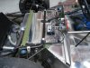
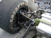
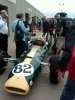
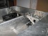
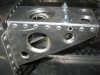
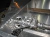
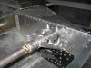
First off staggering work! What a beautiful car you are building, you Kiwi's are the most CAN DO/WILL DO poeple I have ever seen. I have a question/concern I bring up only for safety reasons so please know that it is not to slight the beautiful job you are doing in any way. I have been in the aircraft industry for 25 years most of it in Manufacturing Research and Development and there are small things when working with aluminum that can be a very big deal. The way you deburred leaving scratches will be the first place a crack will start, stress riser. Whenever we get a nick or scratch in structure it must be blended out or replaced so the deburr tool would be a much safer way to go. If you look at the pictures Kiwi Ka posted in post 183 you can see that almost all the rivets used are driven universal type rivets. The reason for this is that they provide both clamp and hole fill while being driven and therefore much better in fatigue. Pop rivets and enen Cherry Max hole filling rivits don't even come close to the strength in either shear or tension. Big pain to drive them all I know, I built an all aluminum airplane a few years ago. The other thing that I think is very critical can also be seen in post 183, the front suspension/shock attach point as well as the rear arm of the upper "A" arm attach point is certainly 4130 Chrom Molly. The loads that will be transfered in this area will be some of the highest in your car and I don't think the aluminum structure you currently have is going to fare to well. I hope you will take this in the spirit it is given, I thought long and hard before taking the time to write this because I trualy love what you are doing and think your skills and attention to detail is surperb! I just don't want to see your beautiful work of art have a suspension failure that could be terrible to say the least. I can't wait to see your future post as I love to follow what other fabricators are doing, your car is fantastic and I can't wait to see it finished. Thanks for sharing your project with us,

Steve
 
Hey Steve, I look at all comments as a positive as I have not found negitive people on this site. I do deburr all holes but I did sand some initially but it was quickly pointed out. The rivets I'm using are Structural Rivets and have a clamp pressure of 1200psi and 700lb shear, 500lb tensile. I did look at a lot of rivets and these were the best pull rivets I could find. The pops are used in places where I can see they were used on the original cars and all my joints use adhessive as well. As for the top rear suspension point, that is still under review and it one of the things I can't find any photos of so not an easy thing to nail down yet. The shock mount and front suspension link actually has a steel inner as I also worried about it being alloy. The thing is that the M20 did away with the steel bulk head that was used in the M8F so I'm trying to keep things as close to original as possible. There are a few things I will do different if I build more than one of these but this car is kind of the prototype. I will keep plugging away at it so any advice is welcome thats what these forums are all about. Cheers Leon
 
Last edited:
Excellent work Leon, that looks like significant progress in terms of time spent on your build.
I have a general question about aluminum sheet metal work I hope you or other members don't mind answering. The radiused holes that you've put into the flat sheet that appear to provide lightness and rigidity, how are they made? I'm imagining a cutting punch with a taper up it's shank that would do the whole process in one hydraulic-powered stroke. I've tried searching on the web and am probably using the wrong terms as I've come up nil.

Keep up the good work and thanks for the inspirational construction of your car.
 
Mass production dies that does the hole and the flare all in once may be available. I can try to explain how manual one-at-a-time dies work.

First the hole is made, deburred and smoothed out.
Two matching dies , an outer and an inner is used next. Providing clearance between the two dies for the specific sheet thickness.

Lightly oil or thin grease the sheet and dies.

Place the die with the stub end through the hole in the sheet. The stub end must be a close fit in the hole but not too tight.

Place the other die on the opposite side of the sheet aligning up with the stub end that is sticking out.

Put in a fly-press and press.

The radius formed is the result of the radius size of the dies.

The size of the radius is specified in tables available from aircraft companies.

Leon may do it differently, but this is how I saw it happen.

Z.C.
 
Sounds great Leon! You are doing such a great job and I always look forward to your updates. Thanks for sharing your journey with us all.

Steve
 
You guys will laugh at me and think I'm cheap ass when I tell you how I do My holes but WTH, The big holes are cut with a hole saw then placed over a 2.5" pipe, then I drive a 2'' pipe with the lip tappered though it, leaves a nice radius. the small holes are .5" drill then the same process as the big hole but I used a wheel nut to create the radius. Cost me nothing and the out come is what I'm looking for.
Cheers Leon.
 

Russ Noble

GT40s Supporter
Lifetime Supporter
Bloody Kiwi cheapskates!. How can a good tool manufacturer ever make a profit?:laugh:

As everyone has said, great work Leon, I love what you are doing. All the best.
 
Good to hear from you Russ, how are going with all the shaking that is still going on down there. I have just come off a hitch and the Mud Engineer is from CHCH and has just been paid out for his house that has been condemned. Hope you are fairing better. Chears Leon
 
Back
Top