
- Forums
- GT40 Replica Manufacturers' Corner
- RCR Forum - RCR40/SLC/917/Superlite Aero
- The SLC Clubhouse
You are using an out of date browser. It may not display this or other websites correctly.
You should upgrade or use an alternative browser.
You should upgrade or use an alternative browser.
Rumbles SLC Build
- Thread starter rumbles
- Start date
-
- Tags
- g50 gear ls3 powernation rumbles slc superlight yellow
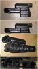
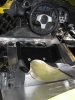
As I look at my pedal assembly, I see spaghetti of hoses and brake lines. So I built a panel to hide all that. It's clamped in place between the master cylinder mounting flanges and the pedal assy.
In addition, I built a dead pedal to hide the suspension pick-up mount.
Very Nice Bill. Thank makes a huge difference and cleans it up nicely! Nice touch.
Very nice. I am having one made for the passenger side too. I have a concern about the hard brake line on the drivers side. As it comes out of the side of the footbox and turns 90 degrees, I have wondered about it interfering with the left foot?
Very nice. I am having one made for the passenger side too. I have a concern about the hard brake line on the drivers side. As it comes out of the side of the footbox and turns 90 degrees, I have wondered about it interfering with the left foot?
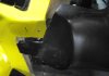
I had the same concerns about the brake like, so I fabricated a left side footrest. This not only afforded me a place to rest my left foot, but it also protected the brake line.
Jim
Attachments
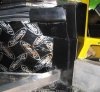
I moved my front brake lines forward to provide some additional room in the foot box ofr driver and passenger.
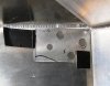
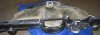
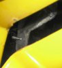
That left a 0.6" hole in the footwell. Fortunately, Steel Rubber Products HQ is just 30 minutes from me and they let me rummage thru their parts. I found a plug to cover the original brake line hole. Steel Rubber Products PN 35-0197-31 works great. You will need to enlarge the hole from 0.6” to 0.75” to use the plug.
In the PIC, see the plug and the new pass-thru for the brakeline.
Attachments
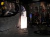
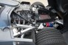
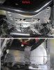
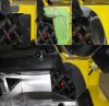
I finally finished the HVAC installation. You may remember, I replaced the VintageAir air box with a Hurricane 1100, so I could tuck it in the far forward section of the passenger footwell. In addition, I put a trunk in the front and moved the radiator and condenser behind the passenger seat. When you make fundamental changes like that, you’ve definitely gone off the reservation and on your own with all the joys of engineering and fabricating every little piece.
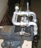
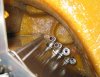
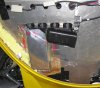
When I installed my fuel tank, I mounted it as far forward as possible. That left just enough room to run the heater and AC lines between the right side of the tank and the chassis. There are some sharp edges there so I rounded them off and added scuff guards. I wanted to completely hide the AC lines, so I ran them thru the passenger pod and up to the top of the footwell. There is very little room to run the lines thru the top of the footwell and then hide them on the inside, so I modeled the bulkhead couplers before drilling the holes. A minor modification to the standard SLC passenger kick panel hid the lines from sight.
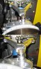
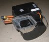
The Hurricane 1100 includes the evaporator/fan and an air plenum with an electronic servo valve to direct air flow to the defroster when needed. Since the hydraulic lift pump is also mounted in the forward footwell, I needed to split the plenum from the evaporator/fan so it would fit in the remaining space. The evaporator/fan is only 8” wide so it leaves lots of legroom. Just 2 other modifications are needed to the evaporator/fan unit:
When I installed my fuel tank, I mounted it as far forward as possible. That left just enough room to run the heater and AC lines between the right side of the tank and the chassis. There are some sharp edges there so I rounded them off and added scuff guards. I wanted to completely hide the AC lines, so I ran them thru the passenger pod and up to the top of the footwell. There is very little room to run the lines thru the top of the footwell and then hide them on the inside, so I modeled the bulkhead couplers before drilling the holes. A minor modification to the standard SLC passenger kick panel hid the lines from sight.
The Hurricane 1100 includes the evaporator/fan and an air plenum with an electronic servo valve to direct air flow to the defroster when needed. Since the hydraulic lift pump is also mounted in the forward footwell, I needed to split the plenum from the evaporator/fan so it would fit in the remaining space. The evaporator/fan is only 8” wide so it leaves lots of legroom. Just 2 other modifications are needed to the evaporator/fan unit:
- The condensation drain was moved from the aft to the forward end of the drain pan.
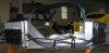
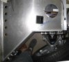
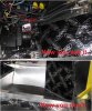
- A small section of the fan exhaust was removed and a small 45 degree air duct was fabricated to direct air up thru a 3”x3” hole that was cut in the top of the footwell.
- An 8” duct was fabricated to carry the air flow to the air plenum with the defroster servo valve.
- The air plenum with the defroster servo is too tall, so I cut it down thru several steps of cut, slash and ABS glue.
- Once I chopped the manhood out of the air plenum, there was no room left for the defroster servo valve, so it was relocated.
- I tried several ways to use the standard SLC boat anchor air duct, but I could not get it to fit with an air tight seal. So I cut off the curved end of the anchor, sealed it to the underside of the dash, and added a 3” inlet duct.
- Then I connected flexible air ducts to the defroster and the 4 dash vents (I added 2 more vents to the center dash panel).
Attachments
-
 IMG_3449.JPG111.8 KB · Views: 575
 -
 IMG_3366.JPG95.8 KB · Views: 593
 -
 IMG_3372.JPG107.1 KB · Views: 512
 -
 IMG_3373.JPG121.7 KB · Views: 560
 -
 IMG_3422.JPG65.5 KB · Views: 559
 -
 IMG_3442.JPG111.2 KB · Views: 540
 -
 AC Plenum.jpg99.3 KB · Views: 518
 -
 IMG_3771.JPG156.1 KB · Views: 568
 -
 IMG_3773.JPG116.4 KB · Views: 510
 -
 HVAC footwell.jpg156.4 KB · Views: 524
 -
 IMG_3781.jpg160.7 KB · Views: 558
Yes, I aligned the front and rear. Using the peep hole in the A-arm as my gauge, I had plenty of rod end thread engagement.
Cool; just fyi, minimum safe thread engagement is 3/4'' on the UCAs and 1'' on the LCAs (steel into aluminum); tie rods you can squeek by at 1/2'' of engagement (steel into steel). Don't want to see those tear our, heh (I think somebody's did because of less than safe thread engagement ... Cam, was that you?)
You must be a hardy soul...It was really cold Saturday morning!
I'm getting the interior ready for upholstery, and lots of other details. I'll post some PICs soon.
Speaking of such, is your GTM in the upholstery shop now?
Pam and I were uptown anyway, and decided to stop by and see if there was anything going on. And yes, it was 24 when we pulled in...:stunned:. My next one will likely be in April or so.
I spoke to Steve on Wednesday or Thursday of last week, and learned that he is still working on the OLDS 442. Apparently the owner keeps adding to the work list. Mine goes in behind that one, and is tentatively scheduled for end of Jan, early Feb.
He said that he was planning to have Murray contact me in the next week or so to start the renderings for the interior.
We'll see.
Mike

They go on the inside of the rear wheel area, parallel to the rear shocks.
Will,
I kinda suspected that, but don't understand how they fit the contour of the rear clam. Does anyone have a PIC of them mounted?
I kinda suspected that, but don't understand how they fit the contour of the rear clam. Does anyone have a PIC of them mounted?
They go on the inside of the rear wheel area, parallel to the rear shocks.
I'll see if I have a picture. If I can find one, I'll post it.
I too had a question on the liners - I've only installed the partial back section as of now. I saved a couple photos from other installs - attached. Part of my dilemma at first was that it appears the large rear clam upper/rear liners is designed for the race tail.... I have the street tail so additional cutting/fabbing looks like my answer.
Attachments
![DSC_7752 [1600x1200].jpg](/data/attachments/56/56904-7e7e95dbedbde5fa91833fdc82eb90c8.jpg?hash=fn6V2-295f)
![IMG_2537 [800x600].jpg](/data/attachments/56/56905-716b76bfb57ebbadde7b5c6416a6eaad.jpg?hash=cWt2v7V-u6)
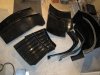
I finished the driver's seat and floor in preparation for upholstery.
- The slider adjustment handle was on the outside of the seat and was kinda ugly, so I wanted to hide it. That meant rebuilding the slider release mechanism so it releases from the inside.
- I plan to upholser the side and rear of the seat mounting brackets so I fabricated aluminum covers.
- I fabricated a raised floor so there is a flat surface for carpet to be laid upon. This also hides the seatbelt attachment hardware.
- I fabricated a small cover behind the e-brake to hide the cables
Attachments
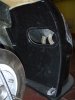
I've been putting some finishing touches on my dash and kick panels.
It's ready for ulphostery!
- I mounted the dash ears via a click-bond fastener, to hide it from view. The fastener is epoxied to the back of the dash ear and then a hole was drilled in the door jam for thru bolting.
- I molded the dash ears into the kick panel.
- First I taped off the area and sketched in the shape I wanted
- I trimmed the dash ear and kick panel to shape
- I shaped and epoxied the some fiberglass scraps I had kept from when other body panels were trimmed.
- Lastly a little body filler
It's ready for ulphostery!
Attachments
Similar threads
- Replies
- 26
- Views
- 8K
- Replies
- 7
- Views
- 6K
- Replies
- 4
- Views
- 10K