
- Forums
- GT40 Replica Manufacturers' Corner
- RCR Forum - RCR40/SLC/917/Superlite Aero
- The SLC Clubhouse
You are using an out of date browser. It may not display this or other websites correctly.
You should upgrade or use an alternative browser.
You should upgrade or use an alternative browser.
S2's Build Thread
- Thread starter sswartz
- Start date
Scott
Lifetime Supporter
I spent a lot of time thinking about the low-pressure fuel system:
Close Out Panel and Brackets
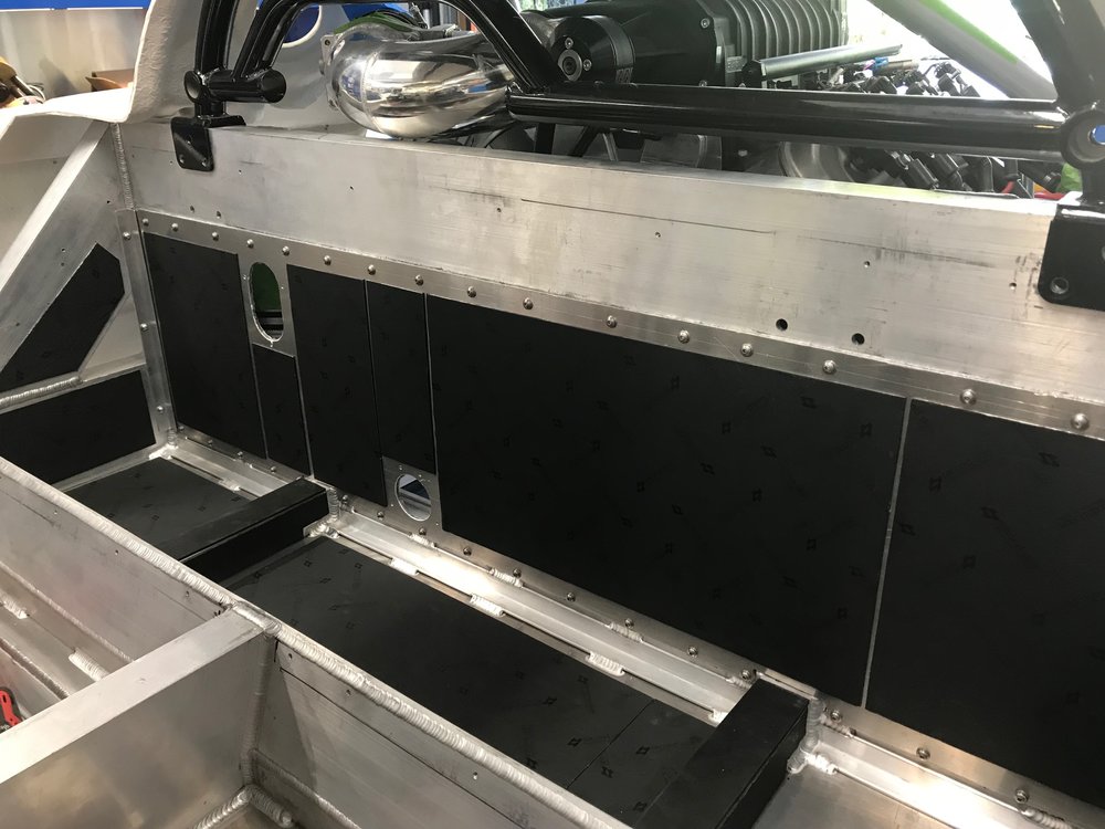

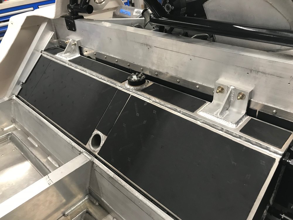
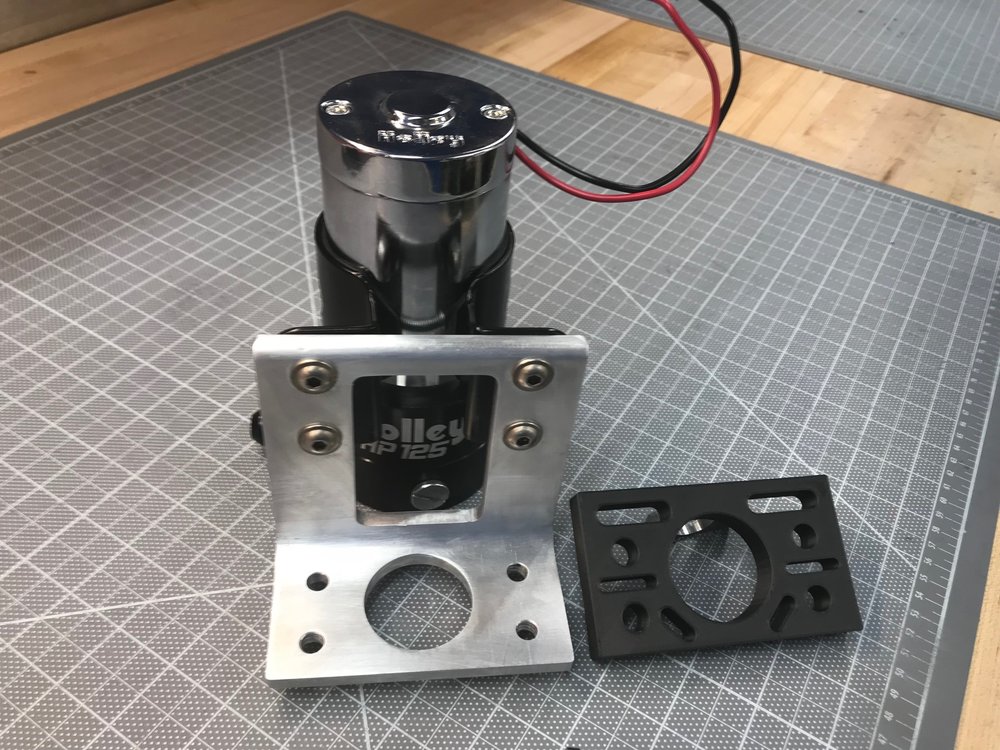
Fuel Pump and Bracket
The fuel pump bracket was made with 1/4" x 4" x 4" angle aluminum. I milled a rectangular opening and drilled a circular one to reduce weight. I also designed and printed a spacer because the pump was too tall for the bracket (a 5" piece would have obviated the need for this). While the pump's mount is coated in rubber, I also created a 1/16" rubber gasket to go under the spacer to further improve vibration isolation.
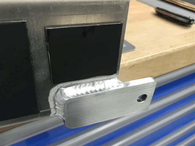
Access Panel
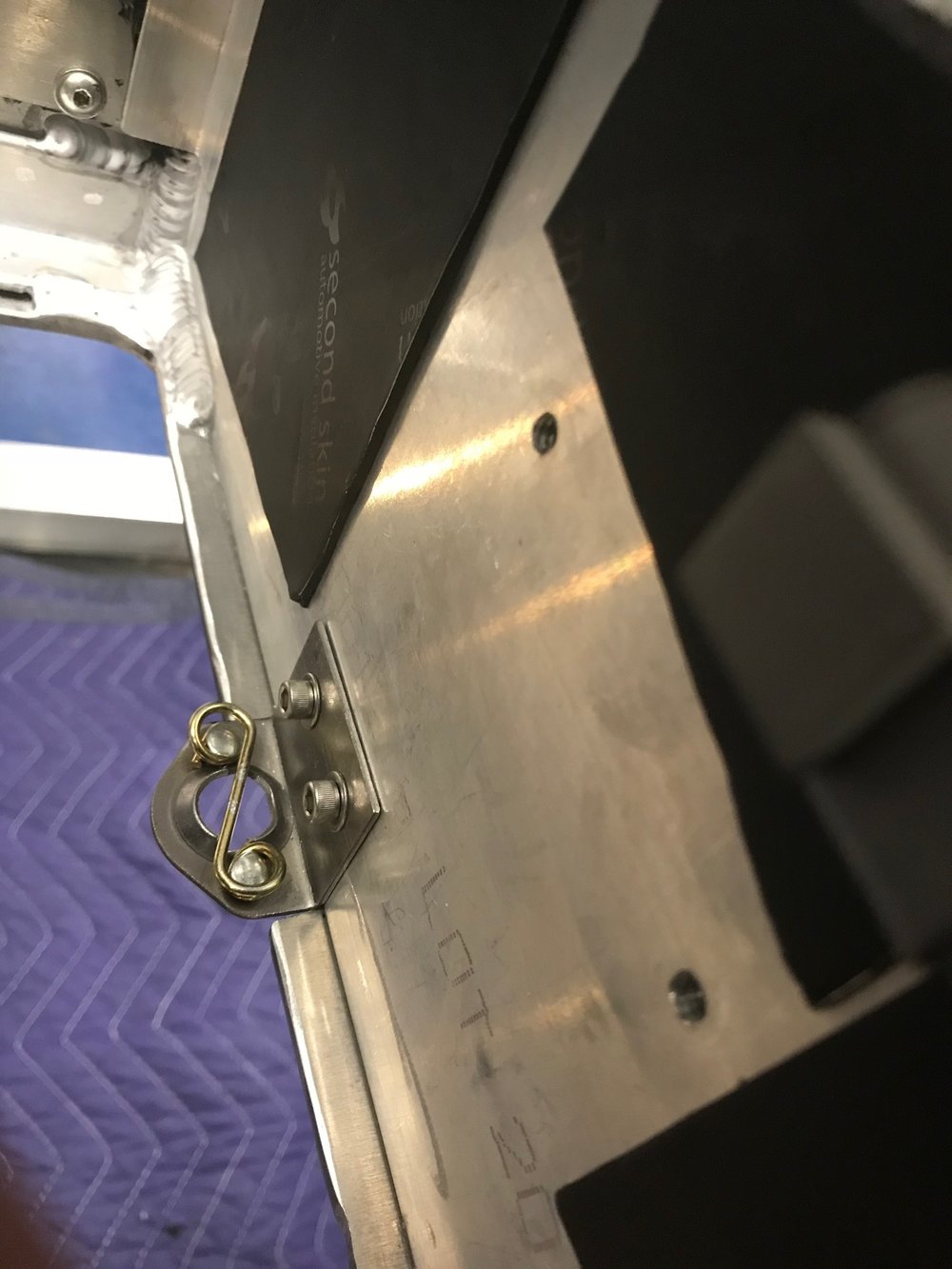
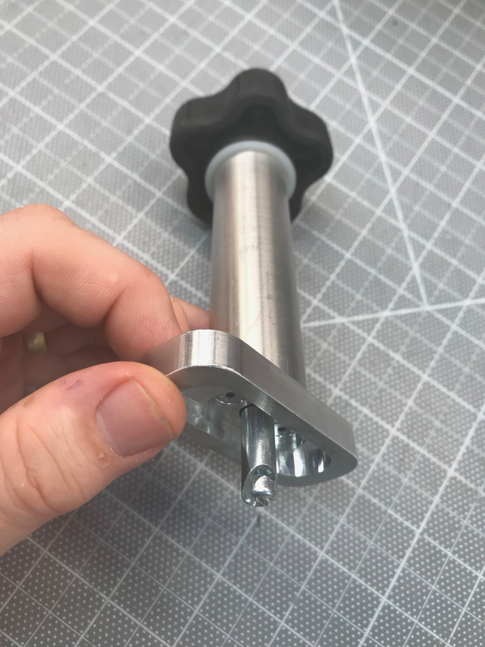
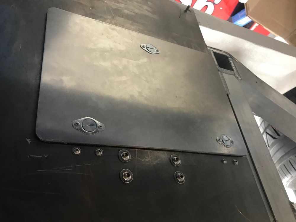
Once the tub is in, the body is on and the surge tank is installed, it's not easy to access the space beside the fuel tank. So, I decided to cut a hole in the floor. To make it easy to remove/install the panel, I decided to use Dzus connectors. Rather than attempt to cut the Dzus profile and holes in the floor I used pre-made Dzus weld plate spring receptacles. Since you can't weld steel to aluminum I simply drilled and tapped the chassis for screws to fasten them. To make up the space between the panel and the fastener I designed and 3D printed some spacers. The spring heights were a little off, so I used a spring height adjust tool below to stretch them a little. This is a lot better than doing it with needle nose pliers.
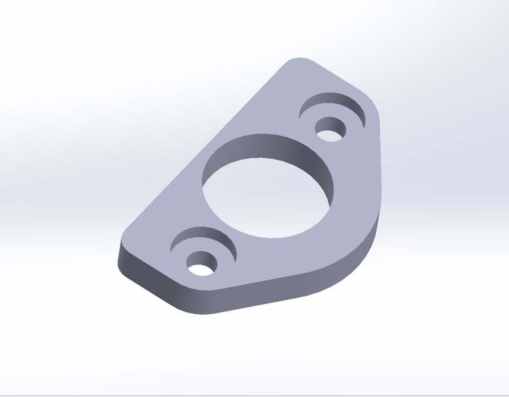
Dzus spacer
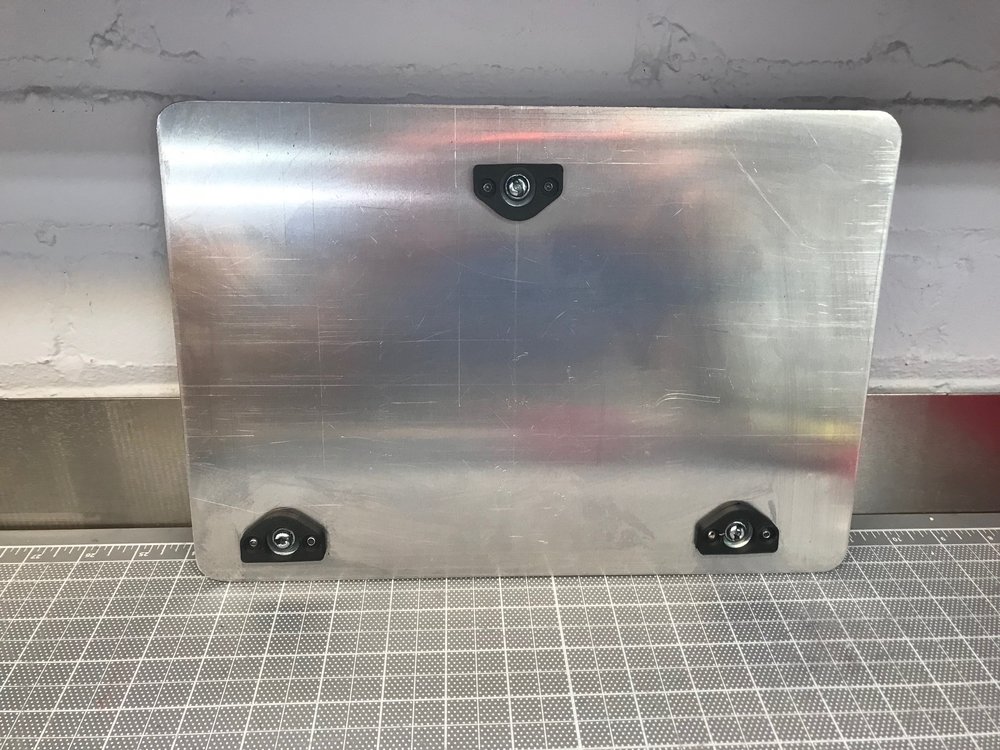
Panel with Dzus spacers riveted on
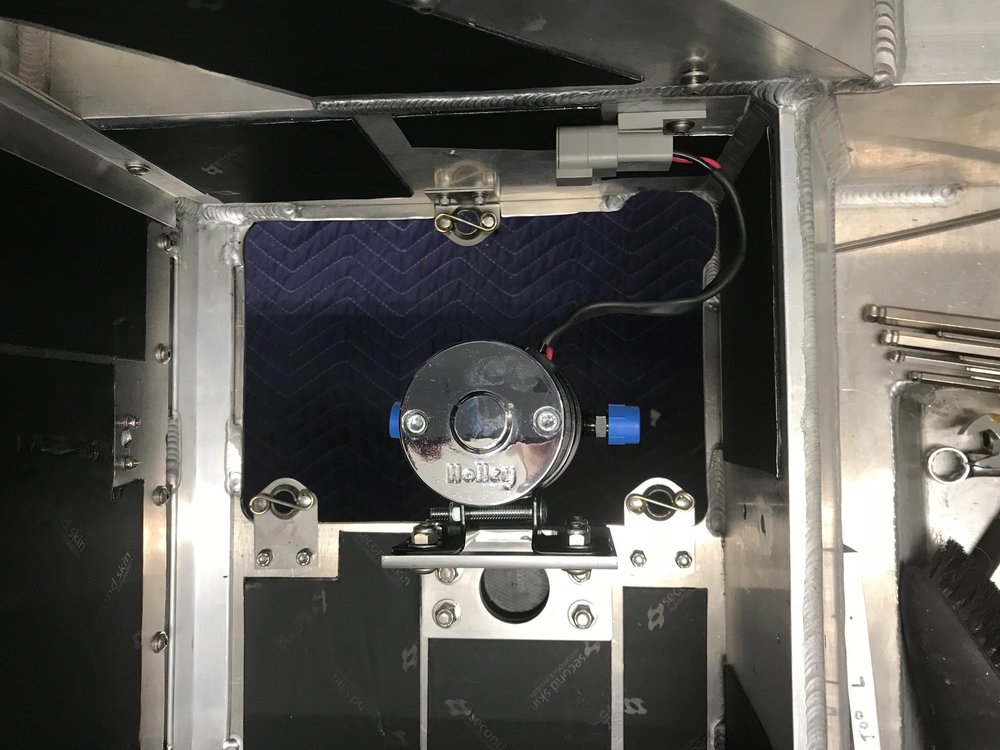
3 spring receptacles mounted
Spring height adjusting tool
Panel installed; the black line between the panel and the bottom of the car looks like a gap, but it's a rubber gasket that's glued to the panel
I wanted to be able to replace the filter element and only need to disconnect one hose connection (rather than disconnecting both ends of the filter and removing the entire assembly). To accomplish this, I tilted the filter bracket downward and ground off the 1/4" lip on the floor so that the filter would clear. It's a close fit, but it works.
Filter mounted with downward angle
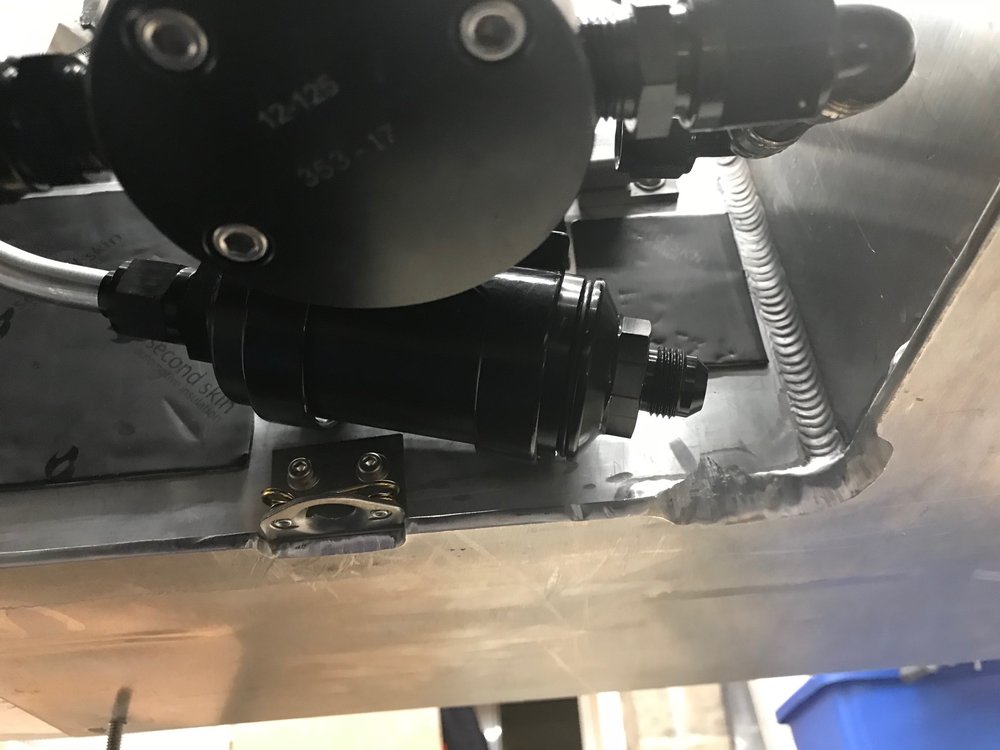
Element is removable with filter mounted

- Fit everything in the space next to the fuel tank
- No "hard-turn" 90-degree bends (i.e., only swept 90s)
- Gravity feed the lift pump; pump inlet 2" lower the fuel tank outlet
- Ability to remove the filter element by removing a single hose connection
- Air-tight panel between engine and fuel tank
- Easy serviceability of filter, pump and all connections
- Fuel shut-off valve accessible in engine compartment
Close Out Panel and Brackets
Fuel Pump and Bracket
The fuel pump bracket was made with 1/4" x 4" x 4" angle aluminum. I milled a rectangular opening and drilled a circular one to reduce weight. I also designed and printed a spacer because the pump was too tall for the bracket (a 5" piece would have obviated the need for this). While the pump's mount is coated in rubber, I also created a 1/16" rubber gasket to go under the spacer to further improve vibration isolation.
Access Panel
Once the tub is in, the body is on and the surge tank is installed, it's not easy to access the space beside the fuel tank. So, I decided to cut a hole in the floor. To make it easy to remove/install the panel, I decided to use Dzus connectors. Rather than attempt to cut the Dzus profile and holes in the floor I used pre-made Dzus weld plate spring receptacles. Since you can't weld steel to aluminum I simply drilled and tapped the chassis for screws to fasten them. To make up the space between the panel and the fastener I designed and 3D printed some spacers. The spring heights were a little off, so I used a spring height adjust tool below to stretch them a little. This is a lot better than doing it with needle nose pliers.
Dzus spacer
Panel with Dzus spacers riveted on
3 spring receptacles mounted
Spring height adjusting tool
Panel installed; the black line between the panel and the bottom of the car looks like a gap, but it's a rubber gasket that's glued to the panel
I wanted to be able to replace the filter element and only need to disconnect one hose connection (rather than disconnecting both ends of the filter and removing the entire assembly). To accomplish this, I tilted the filter bracket downward and ground off the 1/4" lip on the floor so that the filter would clear. It's a close fit, but it works.
Filter mounted with downward angle
Element is removable with filter mounted
Excellent engineering....I like it!:thumbsup:
Scott
Lifetime Supporter
Thanks Dan!
I finished up the rest of the low-pressure fuel system.
I wanted the fuel shut-off valve to be accessible from the engine compartment. To do that, I needed to extend the shaft so that it would pass through the close out panel. I bought a valve from Peterson which is beautifully machined. However, I really didn't like how they implemented the full-open and full-closed stops. When the handle isn't attached, the shaft can be continuously rotated in either direction. As you can see in the picture below, a screw is used to tighten the handle on a round shaft. The full-stop positions are implemented via a fixed pin on the housing which fits into a slot that's machined into the handle. If the handle slips the full-stop positions will be off. While not the end of the world, I went to a lot of trouble to have no restrictions and there is no easy way to know if things are lined up (i.e., full open) once installed.
There must be a better solution. After doing research, I found one from Speedflow. It's not as cool as Peterson's, but the stops are cast into the body and it has a hex shaft which prevents the handle from rotationally slipping. I loosened the screw and was surprised that I couldn't remove the handle. This is because the screw passes through a groove in the shaft. The only way to remove the handle is to remove the screw which is another nice design feature. Extending the shaft was easy using a hex coupler and a cut down 3/16" hex wrench.
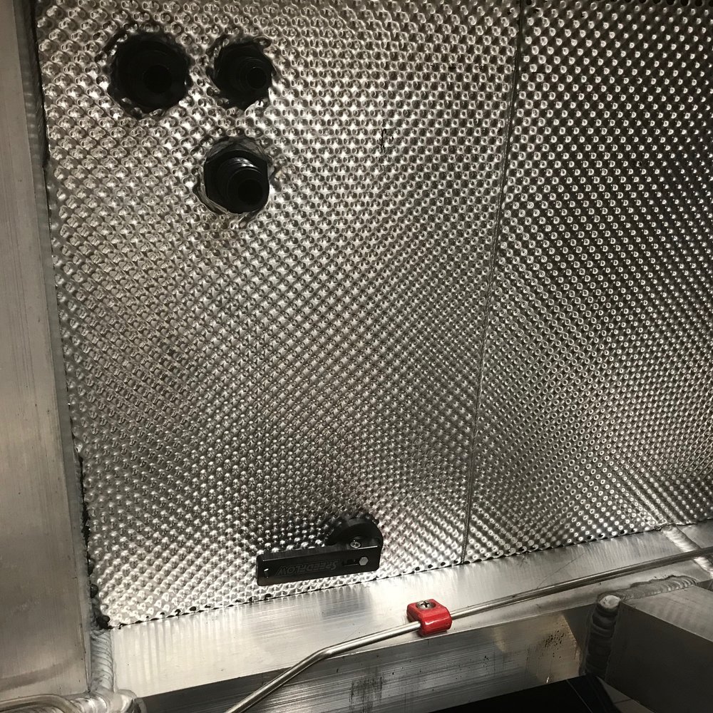
I designed and 3D printed a two-piece cover plate. It prevents any fumes from passing through the closeout panel and any lateral force from being applied to the valve. Oh yeah.... and it it also hides the off-center hole that I drilled
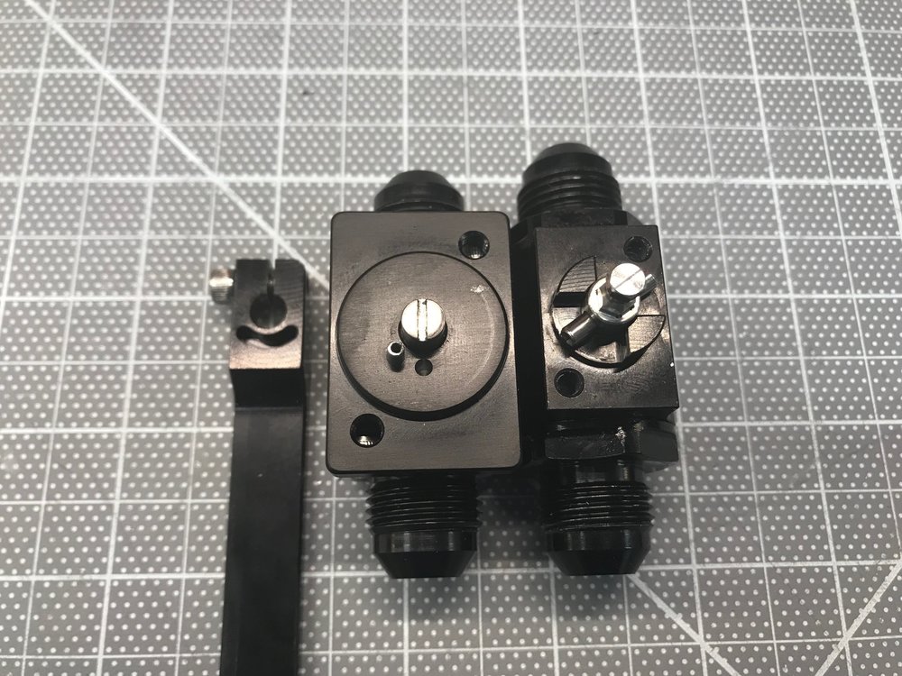
Peterson (left) vs. SpeedFlow (right)

3D-printed cover plate
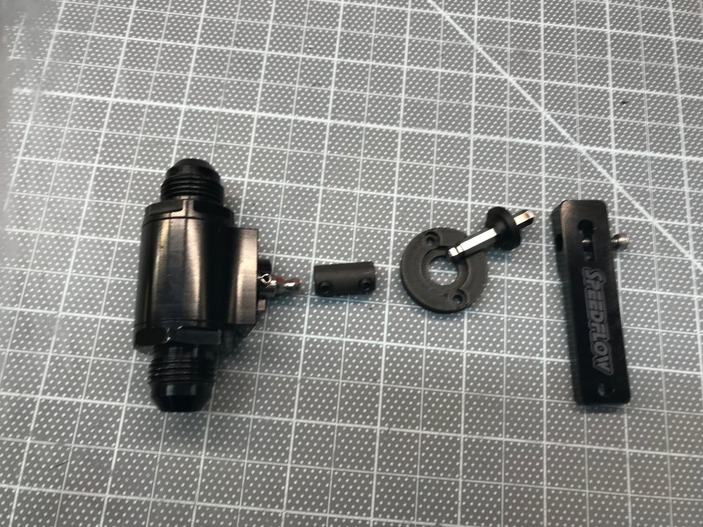
Valve shaft extension parts
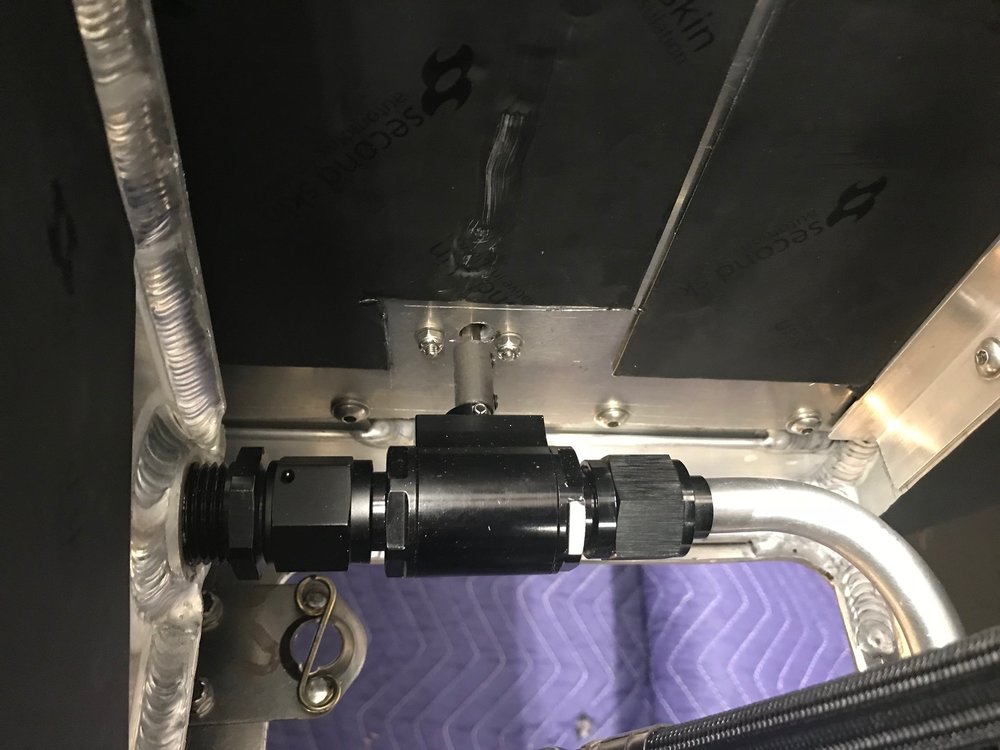
Shut-off valve installed
I raved over how great aramid-braided PFTE hose and fittings were in a previous post. I still really like that stuff, but Abe brought over his hydraulic crimper, a bunch of XRP hose and bags of XRP crimp fittings. You simply cut the hose with a single snip (no mess, no fraying), slide the end on, orient it the way you want, crimp it and use a micrometer to ensure that the OD is within range. Wow, that's easy. The crimp-style hose ends are smaller and lighter than the reusable AN fittings. In addition, since the crimper applies 35 tons of pressure, it also creates a superior connection.
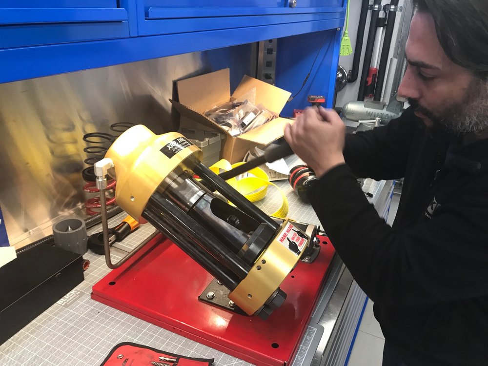
Problem is that the machine costs several thousand dollars and you need a die, which costs hundreds of dollars, for every size fitting. So Abe's my new best friend;-)
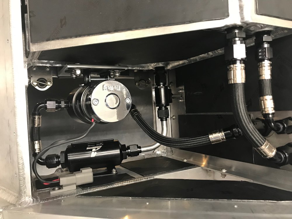
The last step was to install the lines for the fuel out, fuel in and fuel tank vent. I needed to make one hard line to make it work. The filter element is trivial to service and everything is serviceable. I also added heat shrink tubing and Deutsch connector to the fuel pump.
I finished up the rest of the low-pressure fuel system.
I wanted the fuel shut-off valve to be accessible from the engine compartment. To do that, I needed to extend the shaft so that it would pass through the close out panel. I bought a valve from Peterson which is beautifully machined. However, I really didn't like how they implemented the full-open and full-closed stops. When the handle isn't attached, the shaft can be continuously rotated in either direction. As you can see in the picture below, a screw is used to tighten the handle on a round shaft. The full-stop positions are implemented via a fixed pin on the housing which fits into a slot that's machined into the handle. If the handle slips the full-stop positions will be off. While not the end of the world, I went to a lot of trouble to have no restrictions and there is no easy way to know if things are lined up (i.e., full open) once installed.
There must be a better solution. After doing research, I found one from Speedflow. It's not as cool as Peterson's, but the stops are cast into the body and it has a hex shaft which prevents the handle from rotationally slipping. I loosened the screw and was surprised that I couldn't remove the handle. This is because the screw passes through a groove in the shaft. The only way to remove the handle is to remove the screw which is another nice design feature. Extending the shaft was easy using a hex coupler and a cut down 3/16" hex wrench.
I designed and 3D printed a two-piece cover plate. It prevents any fumes from passing through the closeout panel and any lateral force from being applied to the valve. Oh yeah.... and it it also hides the off-center hole that I drilled
Peterson (left) vs. SpeedFlow (right)
3D-printed cover plate
Valve shaft extension parts
Shut-off valve installed
I raved over how great aramid-braided PFTE hose and fittings were in a previous post. I still really like that stuff, but Abe brought over his hydraulic crimper, a bunch of XRP hose and bags of XRP crimp fittings. You simply cut the hose with a single snip (no mess, no fraying), slide the end on, orient it the way you want, crimp it and use a micrometer to ensure that the OD is within range. Wow, that's easy. The crimp-style hose ends are smaller and lighter than the reusable AN fittings. In addition, since the crimper applies 35 tons of pressure, it also creates a superior connection.
Problem is that the machine costs several thousand dollars and you need a die, which costs hundreds of dollars, for every size fitting. So Abe's my new best friend;-)
The last step was to install the lines for the fuel out, fuel in and fuel tank vent. I needed to make one hard line to make it work. The filter element is trivial to service and everything is serviceable. I also added heat shrink tubing and Deutsch connector to the fuel pump.
Scott
Lifetime Supporter
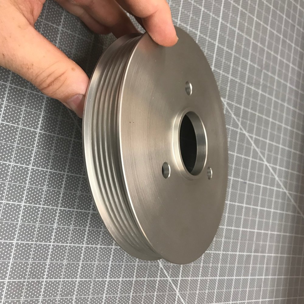
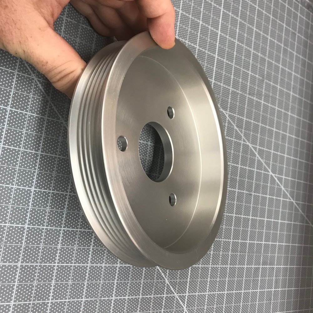
I spent a lot of time Googling on "custom billet pulley" and found lots of companies making beautiful pulleys, but all that I spoke with are focused on products and not one-off pulleys. Anyone with a CNC lathe can make one, but I wasn't sure of the profile of the ribs. I eventually found ASP Racing. They make one-off pulleys and were great to deal with.
According to Vintage Air the ideal pulley diameter for the SD-7B10 compressor which ships with the kit is 6-1/4".
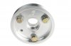
Clear anodized machined finish:
According to Vintage Air the ideal pulley diameter for the SD-7B10 compressor which ships with the kit is 6-1/4".
Clear anodized machined finish:
Scott
Lifetime Supporter
AIR JACK SYSTEM
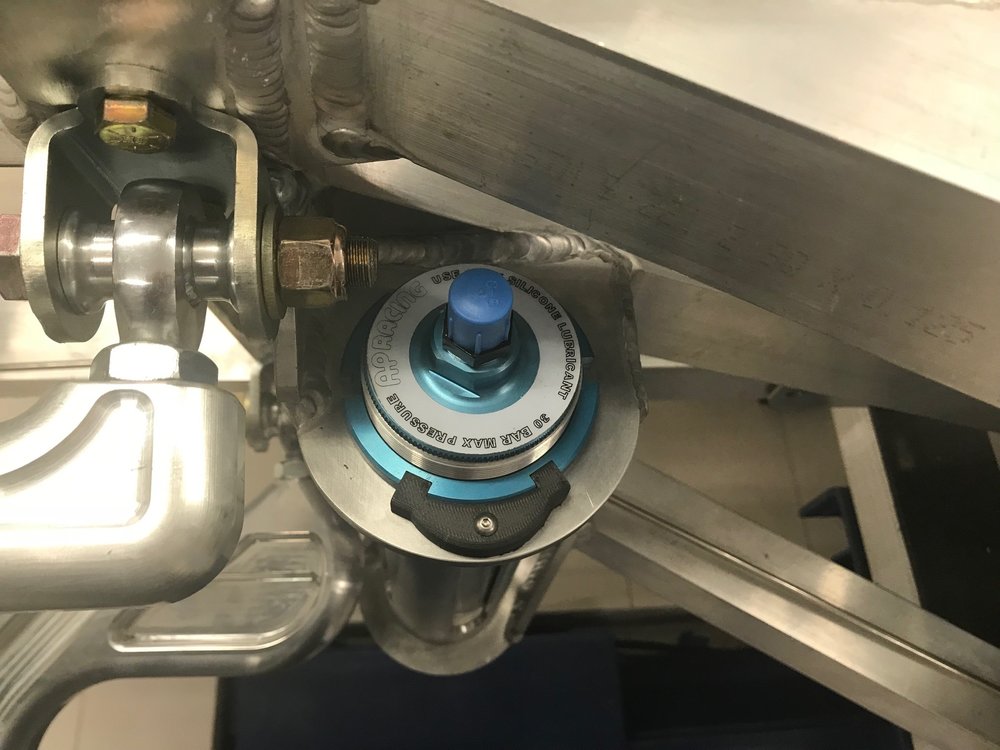
I don't need an air jack system, but I've always wanted one. After doing some research and talking with "H", the chief mechanic for the Robertson Racing Team, I decided to go with a system from AP Racing. They aren't the most expensive ones, but if they're good enough for a team that podiumed at Le Mans, then they’re good enough for me. AP Racing offers three stroke options and I went with the 230 mm (9.0") stroke. The other decision was if I should go with built-in exhaust valves. They automatically sense when pressure is being released in the system and vent the air at the top of the cylinder rather than having it all flow through the single inflation port. This allows the car to slam down fast which is great when you have a professional pit-stop crew, but not ideal for me. In addition, it increases the size, weight and cost, so I went with the non-vented version... who said I can't be practical on this build?
Each jack lifts 675 Kg (1,488 pounds). While two could theoretically lift the car, that would be quite a balancing act. Since a triangle is more stable than a rectangle on uneven ground and three jacks have more than enough capacity, I opted for three rather than four, two in the rear by the engine and one in the front of the foot box.
There are two obvious places to locate the rear air jacks; immediately in front of the lower rear control arms or aft of the rear billet uprights (i.e., the ones engraved with Superlite). Attaching them to the rear billet uprights is the easiest path, but I'm planning on significantly modifying the tail and I didn't want to add any complexity to that area. Placing them in front of the rear control arm keeps them out of the way and moves their modest weight forward. The only downside to that location is that it requires a lot of fabrication and welding.
I contacted Hill McCarty at Agile Automotive Performance who's built multiple race SL-Cs. He used used four of the same AP Racing jacks on all of the cars and I decided to copy the approach he used to mount the rear jacks on the RMS Greenix car. He creates a strong truss by sandwiching a tube between the upper and lower mounting brackets. So I ordered three custom-machined aluminum tubes from him which are bored to perfectly fit the air jacks and slotted to reduced weight. Hill has been a great help and it’s nice to have a endurance-race-proven solution.
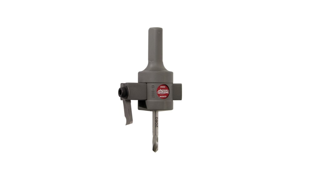
The OD of the air jack body doesn't match up with any available hole saw. To get a good fit I considered using an under-sized hole saw and then opening it up with a sanding drum or having the brackets cut on a water jet. In the end, I bought a trepanning hole cutter (VAL CUT 2000-13) which has an infinitely adjustable arm that holds a carbide cutter. It is capable of cutting a perfect 3/4" to 3" hole. I found that the optimal speed was faster than what the manual indicated.
There's a lot of structural welding and you really want someone who knows what they're doing. Abe from Select Speed Shop did all of the TIG welding which maxed my garage power... 240v and 180-200 amps.
REAR BRACKETS
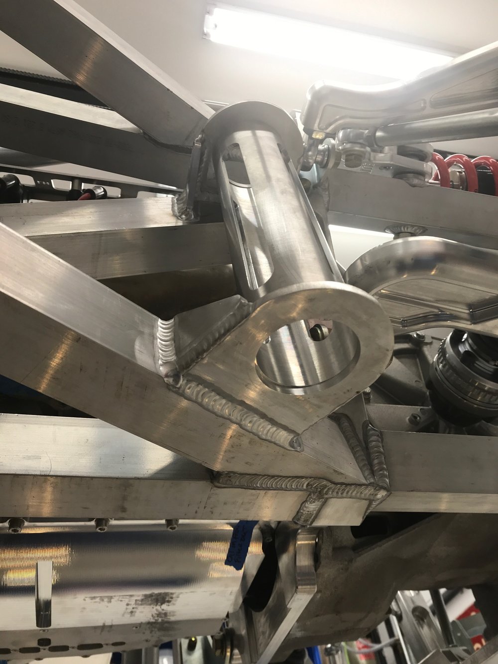
The rear brackets were made from 1/4" x 4" aluminum. Since the upper 2" x 2" tube projects about 1/4” further to the exterior than the lower 2" x 2" tube, it sets the distance of the air jack from the chassis. When fabricating the mounting plate for the upper bracket I was careful to provide enough room so that the mounting ring wouldn’t collide with the weld bead.
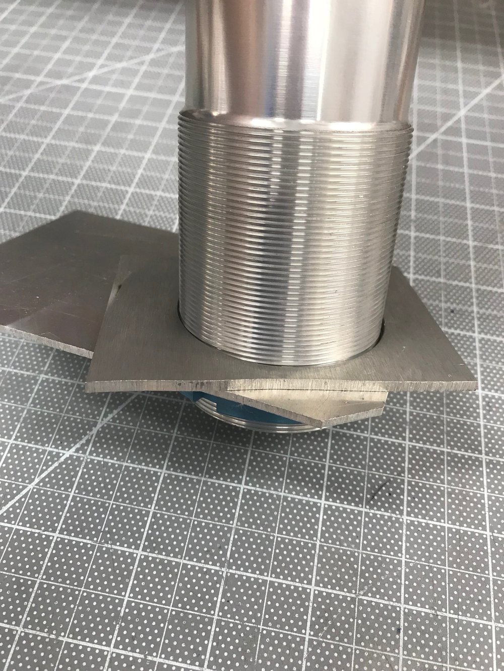
One of the challenges was to figure out how to hold everything in place to determine the size of the mounting plate for the bottom bracket, to ensure that everything was vertical and to weld it. To accomplish this I fabricated a temporary bracket that was clamped to the underside of the bottom 2” x 2” — this worked better than I expected. I also fabricated a spacer to raise the bottom mounting plate up 1/8” to achieve a fillet rather than a billet weld joint. The mounting plates were tack welded with the air jacks in the tubes and their mounting rings tightened. The gussets were fabricated to span the 2” x 2”s and to extend to the middle of the mounting hole. The edges mounting plate by 50% (i.e., 1/8”) to create a edge rather than a butt weld joint.
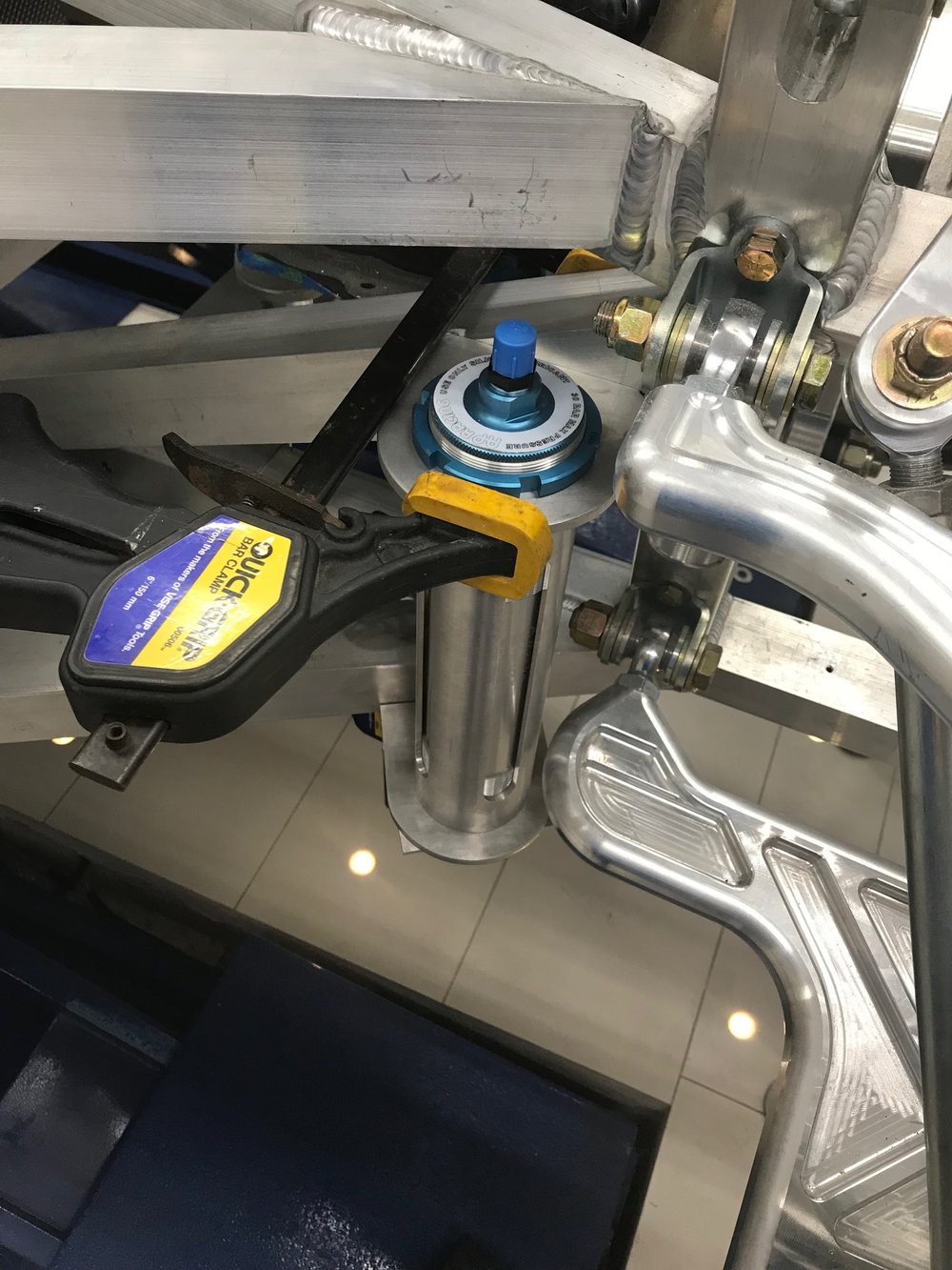
To prepare for final welding, I removed the air jack so that it wouldn’t be damaged by the heat. A pipe clamp was used to replace the tension on the tube created by the air jack’s mounting rings. Finally, the rear suspension was removed. Abe welded everything other than the joints obstructed by the tube. The brackets are a tight fit (exactly what I wanted) and I needed to tap the tube out with a mallet to finish welding the remaining joints.
Temporary holding bracket and 1/8" spacer

Temporary holding bracket clamped to the underside of the bottom 2" x 2"
Upper mounting plate clamped to upper 2" x 2"; ready to start tack welding

Preheating the billet piece with a torch; note jack replaced with pipe clamp

Tube removed to complete welding

Welding finished
Tube isn't centered on hole; it needs a couple of mallet taps

Mission accomplished
I don't need an air jack system, but I've always wanted one. After doing some research and talking with "H", the chief mechanic for the Robertson Racing Team, I decided to go with a system from AP Racing. They aren't the most expensive ones, but if they're good enough for a team that podiumed at Le Mans, then they’re good enough for me. AP Racing offers three stroke options and I went with the 230 mm (9.0") stroke. The other decision was if I should go with built-in exhaust valves. They automatically sense when pressure is being released in the system and vent the air at the top of the cylinder rather than having it all flow through the single inflation port. This allows the car to slam down fast which is great when you have a professional pit-stop crew, but not ideal for me. In addition, it increases the size, weight and cost, so I went with the non-vented version... who said I can't be practical on this build?
Each jack lifts 675 Kg (1,488 pounds). While two could theoretically lift the car, that would be quite a balancing act. Since a triangle is more stable than a rectangle on uneven ground and three jacks have more than enough capacity, I opted for three rather than four, two in the rear by the engine and one in the front of the foot box.
There are two obvious places to locate the rear air jacks; immediately in front of the lower rear control arms or aft of the rear billet uprights (i.e., the ones engraved with Superlite). Attaching them to the rear billet uprights is the easiest path, but I'm planning on significantly modifying the tail and I didn't want to add any complexity to that area. Placing them in front of the rear control arm keeps them out of the way and moves their modest weight forward. The only downside to that location is that it requires a lot of fabrication and welding.
I contacted Hill McCarty at Agile Automotive Performance who's built multiple race SL-Cs. He used used four of the same AP Racing jacks on all of the cars and I decided to copy the approach he used to mount the rear jacks on the RMS Greenix car. He creates a strong truss by sandwiching a tube between the upper and lower mounting brackets. So I ordered three custom-machined aluminum tubes from him which are bored to perfectly fit the air jacks and slotted to reduced weight. Hill has been a great help and it’s nice to have a endurance-race-proven solution.
The OD of the air jack body doesn't match up with any available hole saw. To get a good fit I considered using an under-sized hole saw and then opening it up with a sanding drum or having the brackets cut on a water jet. In the end, I bought a trepanning hole cutter (VAL CUT 2000-13) which has an infinitely adjustable arm that holds a carbide cutter. It is capable of cutting a perfect 3/4" to 3" hole. I found that the optimal speed was faster than what the manual indicated.
There's a lot of structural welding and you really want someone who knows what they're doing. Abe from Select Speed Shop did all of the TIG welding which maxed my garage power... 240v and 180-200 amps.
REAR BRACKETS
The rear brackets were made from 1/4" x 4" aluminum. Since the upper 2" x 2" tube projects about 1/4” further to the exterior than the lower 2" x 2" tube, it sets the distance of the air jack from the chassis. When fabricating the mounting plate for the upper bracket I was careful to provide enough room so that the mounting ring wouldn’t collide with the weld bead.
One of the challenges was to figure out how to hold everything in place to determine the size of the mounting plate for the bottom bracket, to ensure that everything was vertical and to weld it. To accomplish this I fabricated a temporary bracket that was clamped to the underside of the bottom 2” x 2” — this worked better than I expected. I also fabricated a spacer to raise the bottom mounting plate up 1/8” to achieve a fillet rather than a billet weld joint. The mounting plates were tack welded with the air jacks in the tubes and their mounting rings tightened. The gussets were fabricated to span the 2” x 2”s and to extend to the middle of the mounting hole. The edges mounting plate by 50% (i.e., 1/8”) to create a edge rather than a butt weld joint.
To prepare for final welding, I removed the air jack so that it wouldn’t be damaged by the heat. A pipe clamp was used to replace the tension on the tube created by the air jack’s mounting rings. Finally, the rear suspension was removed. Abe welded everything other than the joints obstructed by the tube. The brackets are a tight fit (exactly what I wanted) and I needed to tap the tube out with a mallet to finish welding the remaining joints.
Temporary holding bracket and 1/8" spacer
Temporary holding bracket clamped to the underside of the bottom 2" x 2"
Upper mounting plate clamped to upper 2" x 2"; ready to start tack welding
Preheating the billet piece with a torch; note jack replaced with pipe clamp
Tube removed to complete welding
Welding finished
Tube isn't centered on hole; it needs a couple of mallet taps
Mission accomplished
Scott
Lifetime Supporter
FRONT BRACKET
The front bracket was fabricates using 1/4'“ x 5” angle aluminum and 1/4” x 4” flat aluminum. The first step was to drill a small locating hole for the mounting hole in the right angle. That was uses as a jig to transfer the location of the mounting hole to the floor — is critical that the bracket and hole in the floor are perfectly aligned. To reduce warping the hole was trepanned after the gussets were welded. Since the trepanning cutter needs to be used in a drill press or a mill, the hole in the monocoque was drilled with a 2-3/8” hole cutter and then enlarged with a 2-3/8” sandpaper flap drum.

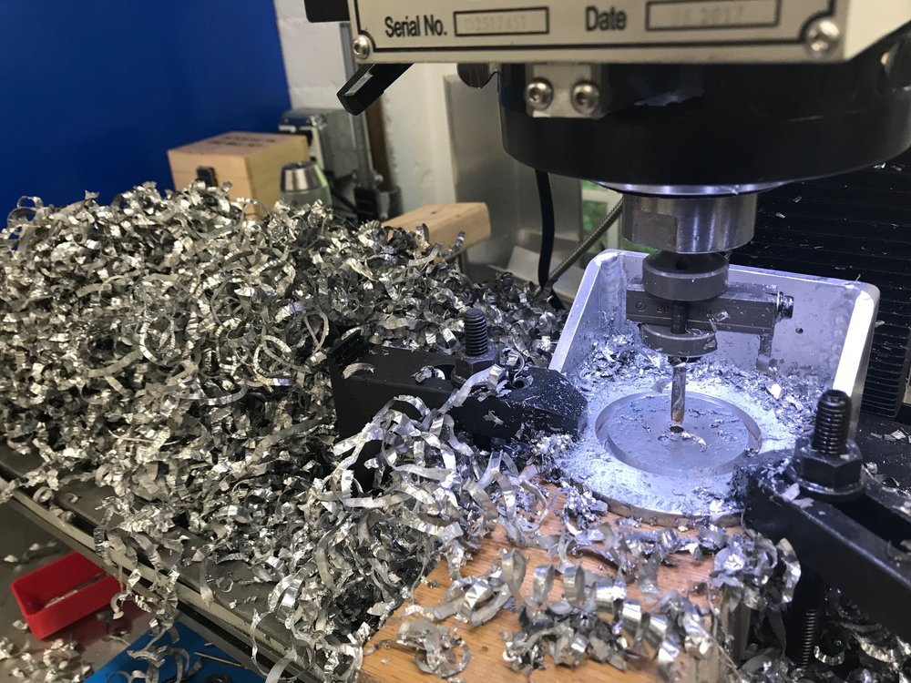
Hole being cut post welding

Finished front bracket

1/4" plate welded to floor, a bit overkill
Installed in monocoque floor
I had to notch the removable floor in the radiator box

Front bracket mounted with four 5/16" grade 8 bolts
The front bracket was fabricates using 1/4'“ x 5” angle aluminum and 1/4” x 4” flat aluminum. The first step was to drill a small locating hole for the mounting hole in the right angle. That was uses as a jig to transfer the location of the mounting hole to the floor — is critical that the bracket and hole in the floor are perfectly aligned. To reduce warping the hole was trepanned after the gussets were welded. Since the trepanning cutter needs to be used in a drill press or a mill, the hole in the monocoque was drilled with a 2-3/8” hole cutter and then enlarged with a 2-3/8” sandpaper flap drum.
Hole being cut post welding
Finished front bracket
1/4" plate welded to floor, a bit overkill
Installed in monocoque floor
I had to notch the removable floor in the radiator box
Front bracket mounted with four 5/16" grade 8 bolts
Scott
Lifetime Supporter
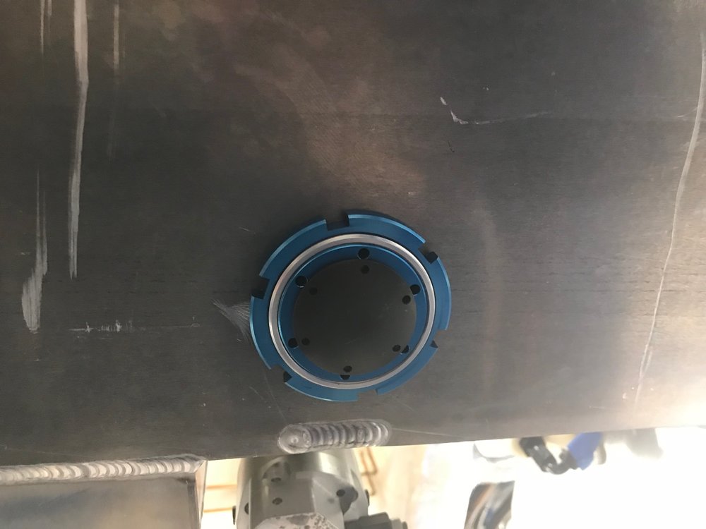
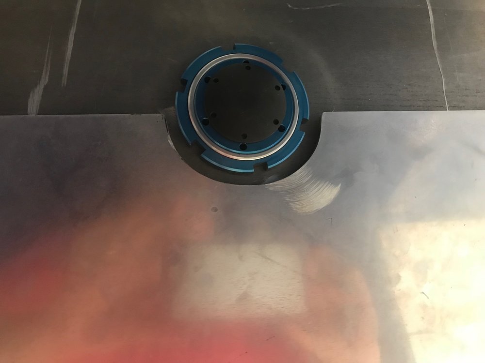
I designed and 3D printed a locking ring to prevent the air jack mounting rings from loosening. They don’t take any force so a 6-32 screw was used to keep them from rotating.
In the last post I notched the removable floor in the nose to clear the front floor jack. I created a 360-degree lock that spans the gap between the mounting ring and the floor to reduce drag… oh, and it just happens to hide my less than perfect notch ;-)
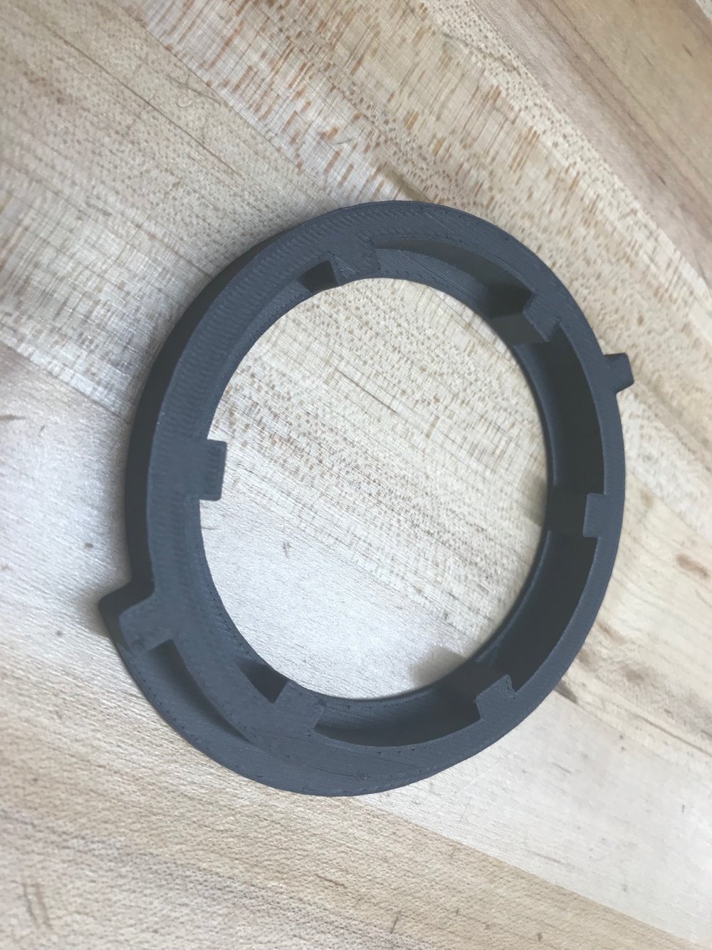
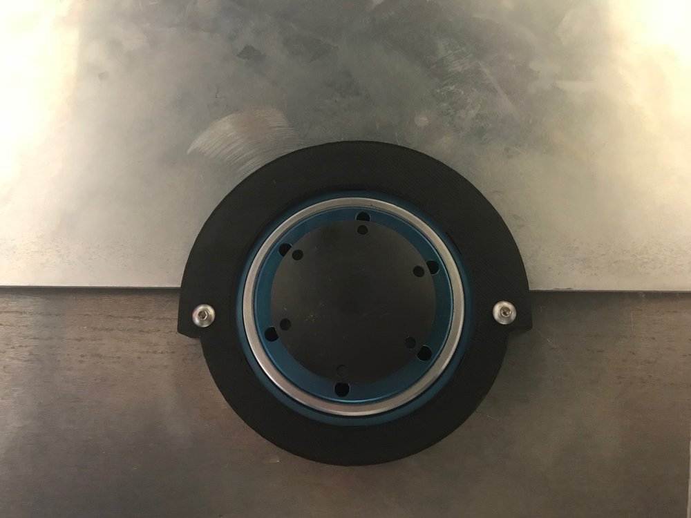
In the last post I notched the removable floor in the nose to clear the front floor jack. I created a 360-degree lock that spans the gap between the mounting ring and the floor to reduce drag… oh, and it just happens to hide my less than perfect notch ;-)
Scott
Lifetime Supporter
Does anyone know if the Superlite parking brake caliper/bracket works with the Brembo GT brake upgrade? The caliper bottoms out on the rotor (i.e., the bracket doesn't place the caliper far enough from the center of the rotor). If I insert a flat 0.375” spacer between the bracket and the upright everything looks fine. Maybe the Brembo GT rotors have a larger diameter? Mine are 380mm… thoughts?
Scott
Lifetime Supporter
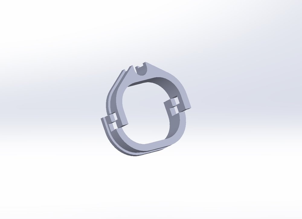
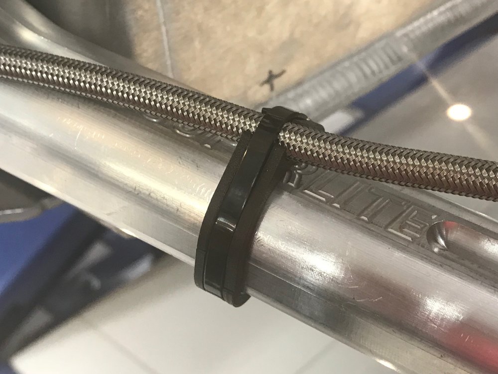
I needed to attach the hydraulic line for the front lift to the lower control arm. A zip tie looked a little naked and I didn’t want to use a P-clip because I’d have to drill and tap the control arm. So I decided to design one. My initial thought was to make something with a snap hinge, but that made it too bulky and not as durable as a zip tie. I wound up with two pieces that snap together on the control arm and have a recessed channel for a zip tie.
Ken Roberts
Supporter
Scott is this guy 3d printing a model of your car?
Scott
Lifetime Supporter
Finally a coffee table book worth having! High-speed pictures of dogs catching treats. Sure to put a smile on you face.
https://www.cnn.com/interactive/2018/11/entertainment/dogs-catching-treats-cnnphotos/
https://www.cnn.com/interactive/2018/11/entertainment/dogs-catching-treats-cnnphotos/
Peter, that's Kevin who I've been working with to design my new tail. He's very talented!
A friend was pushed over the decision making edge by Peter's video, he bought the same piece of equipment after viewing.

Scott
Lifetime Supporter
Mesa, IMO he should also pick up a copy of Simplify3D. Everyone one I know (consumers and maker spaces) use it. I used to use it with my old printer (my current one has a integrated cloud-based slicer) and Kevin's using it in the video. At $149 it's money well spent vs. the free ones.
Scott
Lifetime Supporter
I purchased the option parking brake kit from Superlite with the intention of adding an E-Stopp. I spent a lot of time thinking about where to location the E-Stopp so that it would be serviceable and one of Stephen’s forum posts provided the answer. He mounted the unit in the recessed floor which affords easy access for maintenance. I was already planning on creating a closeout panel that wrapped around the chair to create a flat floor. I figured it would be a great place for luggage. I figured I could could fit a T-shirt, boxers, socks and toothbrush is a Ziploc bag LOL. Stephen also fabricated a channel to protect the cables… brilliant!
So that was the plan until I spoke with Allan and Bob. Allan has successfully used the E-Stopp in multiple cars, but he’s had two cars in which he couldn’t reliably get the parking brake to hold. He called the manufacturer to see if he could increase the 600-pound tension and they indicated that they’d have to completely redesign the unit. Bob also had similar issues and his car let loose while on a trailer. He spent a fair amount of time trying to get it to work reliably to no avail. While many people have had success with the E-Stopp, two very talented builders have had issues with it while the car was in the build stage.
Back to the drawing board. I then discovered motor-on-caliper parking brakes. Instead of using a cable to actuate the caliper these systems utilize an ECU to drive motors that are directly attached to the calipers. Apparently TRW has shipped over 60 million units and Brembo and other manufacturers have integrated the motor directly into the hydraulic caliper. This reduces unsprung weight by removing the need for a separate caliper and bracket. It’s my understanding that some systems implement a true emergency brake by using accelerometers to ensure that the car doesn’t spin when the brake is applied.
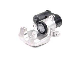
TRW motor-on-caliper VW Passat e-Brake

Brembo electric motor integrated with hydraulic caliper
The TRW looked like an ideal solution. I tried to buy an aftermarket version or at least get documentation on an OEM version to no avail. So to the junk yard I went. It’s easy to pull the calipers and ECU, but I couldn’t figure out how to activate them. I tried using a CAN bus sniffer on a running car to figure which CAN bus messages where used to activate and deactivate the brake. My conclusion was that that the e-brake ECU are typically deeply integrated into the OEM’s system and that it wasn’t going to be as easy as finding two messages and broadcasting them. There’s likely a OEM implementation out there that might be that simple, but god knows how long it would take to find.
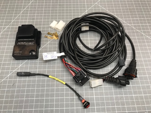
So after over a year of intermittent researching and tinkering I ordered an E-Stopp. On the day it arrived I decided to do one final search before opening the box and installing it following Stephen’s method…. AND I found a standalone solution that from HiSpec that includes two calipers and an ECU. At £640.00 (~$835.00) they’re a good value given that the Superlite option costs $999 and an E-Stopp costs $479.00. They offer multiple rotor widths and colors and quote 28 days to manufacturer plus shipping/customs from the UK.
So that was the plan until I spoke with Allan and Bob. Allan has successfully used the E-Stopp in multiple cars, but he’s had two cars in which he couldn’t reliably get the parking brake to hold. He called the manufacturer to see if he could increase the 600-pound tension and they indicated that they’d have to completely redesign the unit. Bob also had similar issues and his car let loose while on a trailer. He spent a fair amount of time trying to get it to work reliably to no avail. While many people have had success with the E-Stopp, two very talented builders have had issues with it while the car was in the build stage.
Back to the drawing board. I then discovered motor-on-caliper parking brakes. Instead of using a cable to actuate the caliper these systems utilize an ECU to drive motors that are directly attached to the calipers. Apparently TRW has shipped over 60 million units and Brembo and other manufacturers have integrated the motor directly into the hydraulic caliper. This reduces unsprung weight by removing the need for a separate caliper and bracket. It’s my understanding that some systems implement a true emergency brake by using accelerometers to ensure that the car doesn’t spin when the brake is applied.
TRW motor-on-caliper VW Passat e-Brake
Brembo electric motor integrated with hydraulic caliper
The TRW looked like an ideal solution. I tried to buy an aftermarket version or at least get documentation on an OEM version to no avail. So to the junk yard I went. It’s easy to pull the calipers and ECU, but I couldn’t figure out how to activate them. I tried using a CAN bus sniffer on a running car to figure which CAN bus messages where used to activate and deactivate the brake. My conclusion was that that the e-brake ECU are typically deeply integrated into the OEM’s system and that it wasn’t going to be as easy as finding two messages and broadcasting them. There’s likely a OEM implementation out there that might be that simple, but god knows how long it would take to find.
So after over a year of intermittent researching and tinkering I ordered an E-Stopp. On the day it arrived I decided to do one final search before opening the box and installing it following Stephen’s method…. AND I found a standalone solution that from HiSpec that includes two calipers and an ECU. At £640.00 (~$835.00) they’re a good value given that the Superlite option costs $999 and an E-Stopp costs $479.00. They offer multiple rotor widths and colors and quote 28 days to manufacturer plus shipping/customs from the UK.
Scott
Lifetime Supporter
It seems to be well built and I was happy to see a quality assurance tag (see picture below) on the harness indicating when and by whom it was tested. The top of the ECU housing appears to be anodized cast aluminum with the backside potted with epoxy to encapsulate the electronics. The included button has an LED to indicate if the brake is engaged or not. It’s useful if you want to hide it or if you’re going with a race car interior, but I’m likely going to upgrade it.
The following photos compare the Superlite caliper (left) to the HiSpec caliper (right).

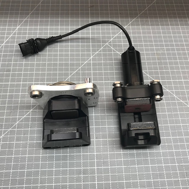


I expected the overall HiSpec system to be lighter, but I expected the calipers to be heavier due to the integral motor. I’m thrilled that the HiSpec solution has lighter calipers which results in lower unsprung weight. The following table lays out the weight for three different parking brake scenarios (assuming the bracket for the HiSpec weighs the same as the Superlite option):

There are three features to prevent accidental engagement/disengagement:
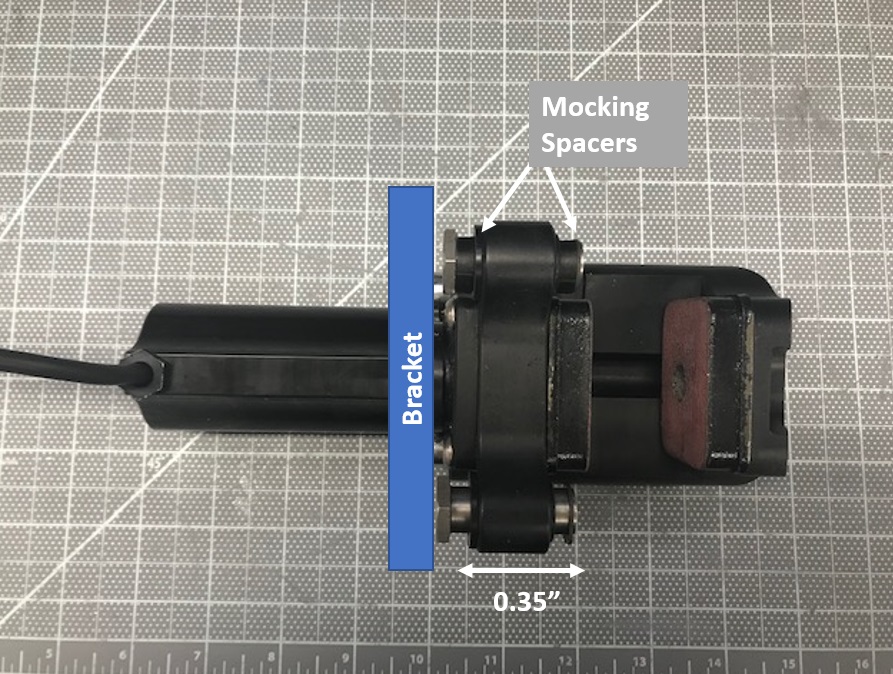
Caliper "float" and mocking spacers

Caliper "float" and brake pad mocking spacers
The rotors are 28 mm wide (1.1”) and the space between the pads is 1.2”. To ensure that the pads were perfectly spaced on the rotor I tried using some metal shims, but they weren’t the exact width that I wanted and they kept falling to the floor. So guess what? I 3D printed two brake pad spacers the prefect width and with a right angle to keep them from falling. The openings in the brake pad spacers aren’t for style points. They significantly reduce print time and the amount of material used. This is the exact opposite of CNC machining in which this would increase machining time.
Since the hydraulic brake caliper is at 3 o’clock I placed the parking brake caliper at 9 o’clock. While mocking the bracket I figured out that it’s critical to locate it in exactly the 9 o’clock position. Otherwise I would will get different fitment due to the curvature of the rotor and the shape of the upright (it’s sloped -15 degrees from vertical). I tried to do everything on the car, but after a couple of misses I decided to pull the upright… I hate removing ball joints. I think I’m going to put some anti-seize on them when I reassemble!
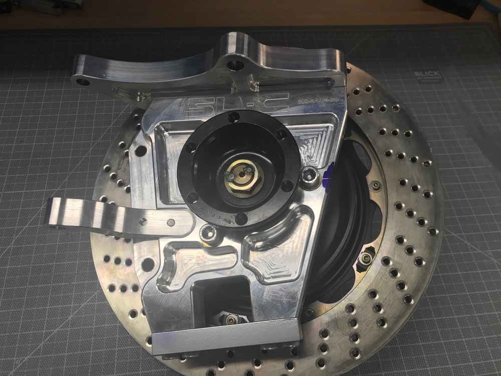
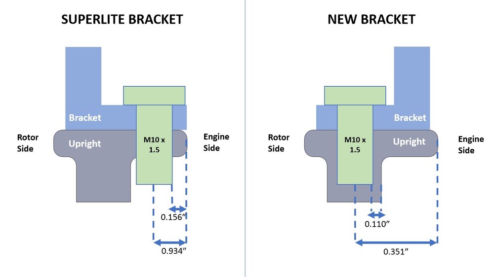
The Superlite bracket requires you to drill holes in the the side of the upright which has machined pockets behind it (i.e., the recesses above and below the 9 o’clock position in the picture above). This area is 0.3” thick which is only 0.95x the diameter of a M10 bolt which is well under the 2x rule of thumb for thread depth in aluminum. Given that the parking bracket doesn’t see much stress and that any stress puts one screw in compression and the other in tension this isn’t an issue. That said, it doesn’t feel right to put the screws there. In any event, the HiSpec caliper results in a bracket that places the screws towards the center of the upright. After careful measuring, it appears that the holes can be placed in the web between the machined pockets on both sides (see picture below). I would like to confirm the 0.934” dimension with Superlite before drilling!
A bunch of iterations I wound up with the following bracket. This could be made from a 3/8” angle aluminum, but the Superlite bracket is machined from billet. If we’re going to machine it, we might as well give it some pockets to make it a little more like the upright!

To hold the mock bracket in place and ensure that it was parallel to the upright’s edge I used a piece of 1/4” scrap aluminum (yeah, that’s not bending). I wanted to position the bracket inboard of the upright’s chamfer so I used some scrap 1/8” aluminum to make a spacer and lined everything up using a centerline groove I designed into the mock bracket.
The following photos compare the Superlite caliper (left) to the HiSpec caliper (right).
I expected the overall HiSpec system to be lighter, but I expected the calipers to be heavier due to the integral motor. I’m thrilled that the HiSpec solution has lighter calipers which results in lower unsprung weight. The following table lays out the weight for three different parking brake scenarios (assuming the bracket for the HiSpec weighs the same as the Superlite option):
There are three features to prevent accidental engagement/disengagement:
- The button must be held for two seconds
- An optional wheel speed input to prevent activation when moving
- An optional ignition input to prevent deactivation
Caliper "float" and mocking spacers
Caliper "float" and brake pad mocking spacers
The rotors are 28 mm wide (1.1”) and the space between the pads is 1.2”. To ensure that the pads were perfectly spaced on the rotor I tried using some metal shims, but they weren’t the exact width that I wanted and they kept falling to the floor. So guess what? I 3D printed two brake pad spacers the prefect width and with a right angle to keep them from falling. The openings in the brake pad spacers aren’t for style points. They significantly reduce print time and the amount of material used. This is the exact opposite of CNC machining in which this would increase machining time.
Since the hydraulic brake caliper is at 3 o’clock I placed the parking brake caliper at 9 o’clock. While mocking the bracket I figured out that it’s critical to locate it in exactly the 9 o’clock position. Otherwise I would will get different fitment due to the curvature of the rotor and the shape of the upright (it’s sloped -15 degrees from vertical). I tried to do everything on the car, but after a couple of misses I decided to pull the upright… I hate removing ball joints. I think I’m going to put some anti-seize on them when I reassemble!
The Superlite bracket requires you to drill holes in the the side of the upright which has machined pockets behind it (i.e., the recesses above and below the 9 o’clock position in the picture above). This area is 0.3” thick which is only 0.95x the diameter of a M10 bolt which is well under the 2x rule of thumb for thread depth in aluminum. Given that the parking bracket doesn’t see much stress and that any stress puts one screw in compression and the other in tension this isn’t an issue. That said, it doesn’t feel right to put the screws there. In any event, the HiSpec caliper results in a bracket that places the screws towards the center of the upright. After careful measuring, it appears that the holes can be placed in the web between the machined pockets on both sides (see picture below). I would like to confirm the 0.934” dimension with Superlite before drilling!
A bunch of iterations I wound up with the following bracket. This could be made from a 3/8” angle aluminum, but the Superlite bracket is machined from billet. If we’re going to machine it, we might as well give it some pockets to make it a little more like the upright!
To hold the mock bracket in place and ensure that it was parallel to the upright’s edge I used a piece of 1/4” scrap aluminum (yeah, that’s not bending). I wanted to position the bracket inboard of the upright’s chamfer so I used some scrap 1/8” aluminum to make a spacer and lined everything up using a centerline groove I designed into the mock bracket.
Similar threads
- Replies
- 10
- Views
- 10K
- Replies
- 4
- Views
- 5K