S2's Build Thread

Scott

Lifetime Supporter
Mild steel chassis tubes are normally 1010.

Niel,
I wasn’t familiar with 1010 so I looked it up in one of Carrol Smith’s books. While he’s not infallible, I find him useful and always highly opinionated…

SAE 1010-1015 “It’s strength levels are moderate and it was never intended to be used as a primary structure – lawn furniture, trailer frames and tooling only!”

SAE 1018-1020 “I use it for just about everything other than suspension links”

SAE 4130 “I believe that not heat treating 4130 fabrications is DUMB… you wind up with an expensive part with the same strength as 1020 and brittle joints”

So, you’re advocating that I use material appropriate for lawn furniture and my approach is DUMB LOL.

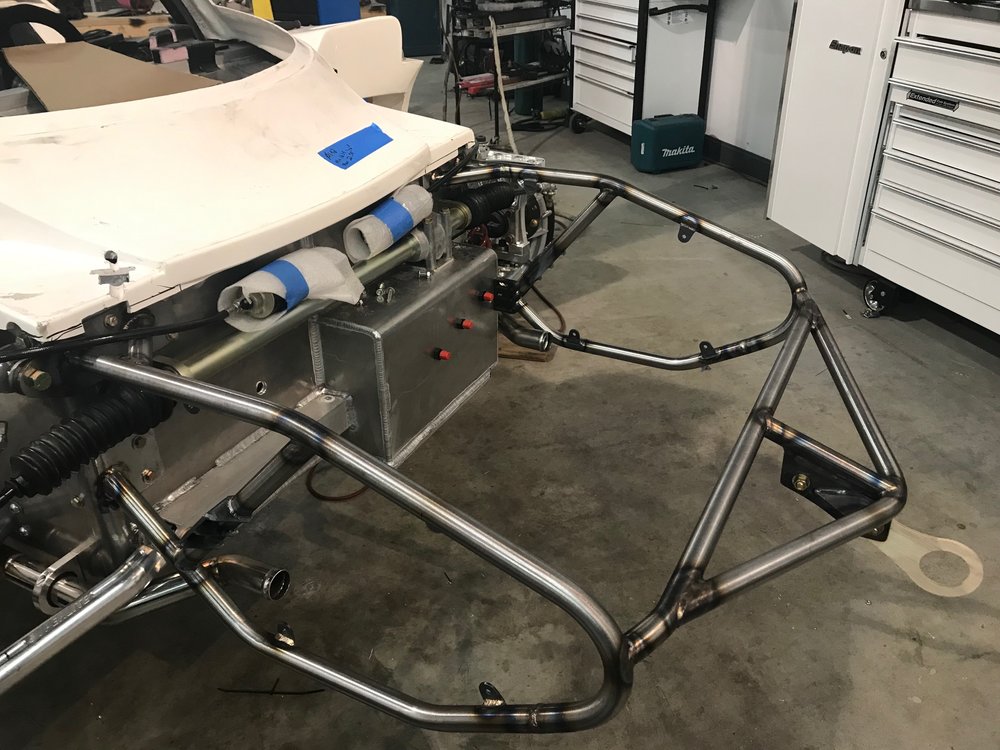
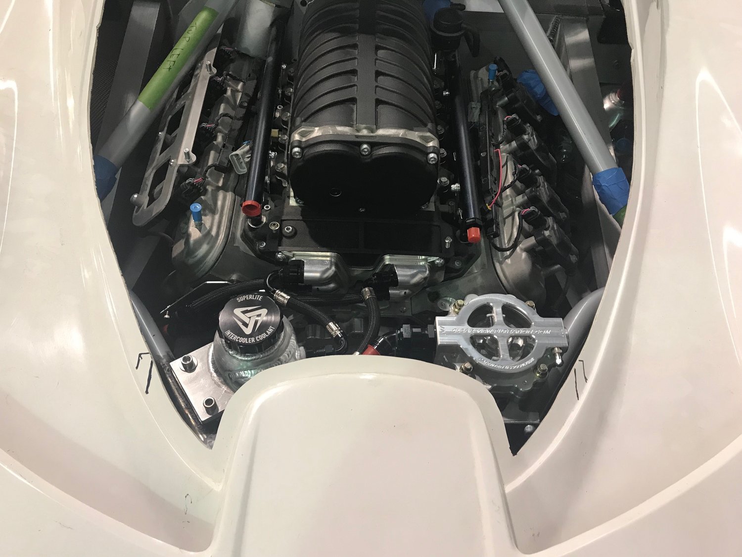
I’m sure that 1010 is fine if you have proper triangulation/geometry and appropriate tube diameter. However, if you look at the pictures in the previous posts, you will note that for fitment reasons I was limited to 1” tube and sub-optimal geometry. While 1010’s elongation % is almost twice that of 4130 or 1020 (i.e., absorbs more energy in plastic deformation) it starts to deform about twice as quickly and it will fail before either begins to deform.

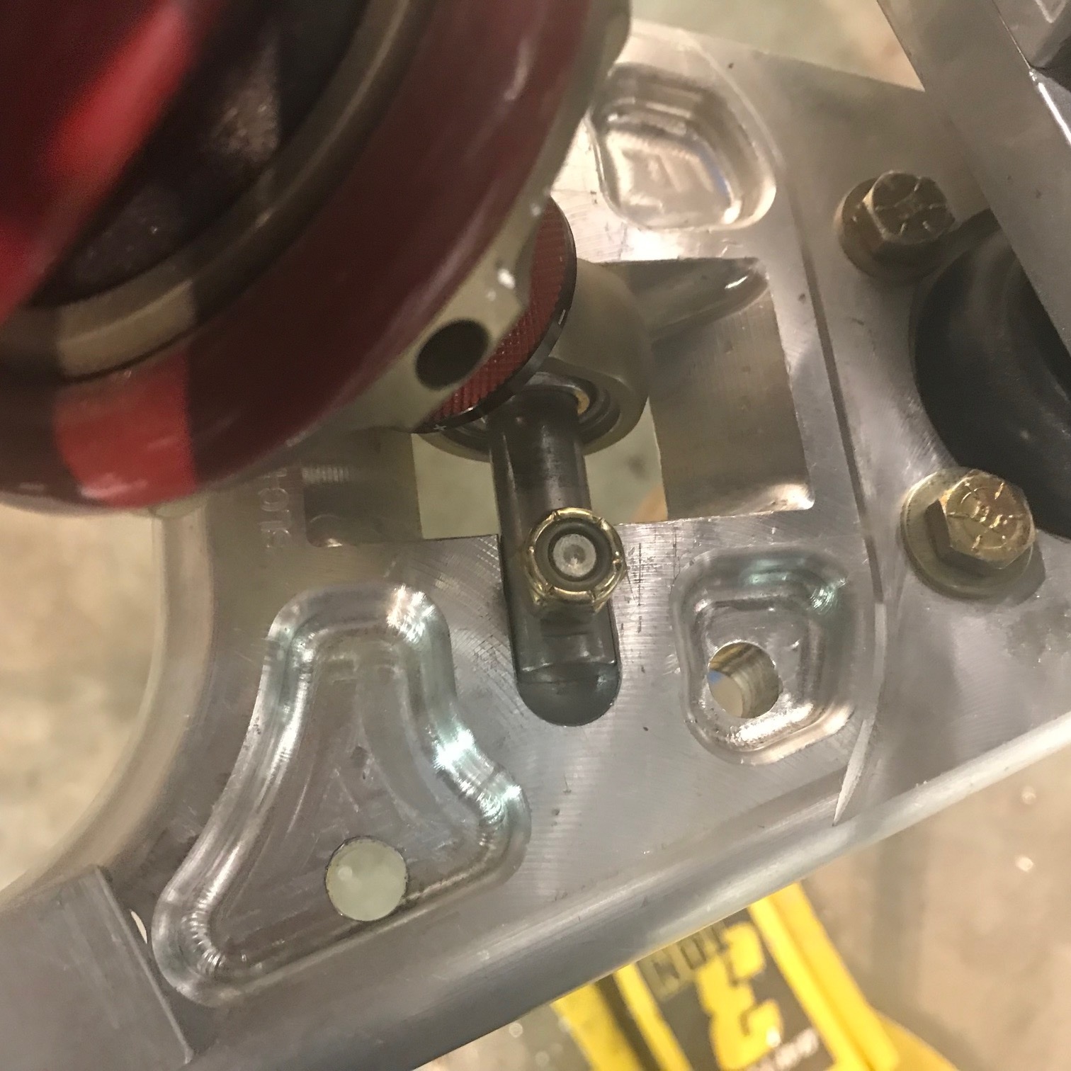
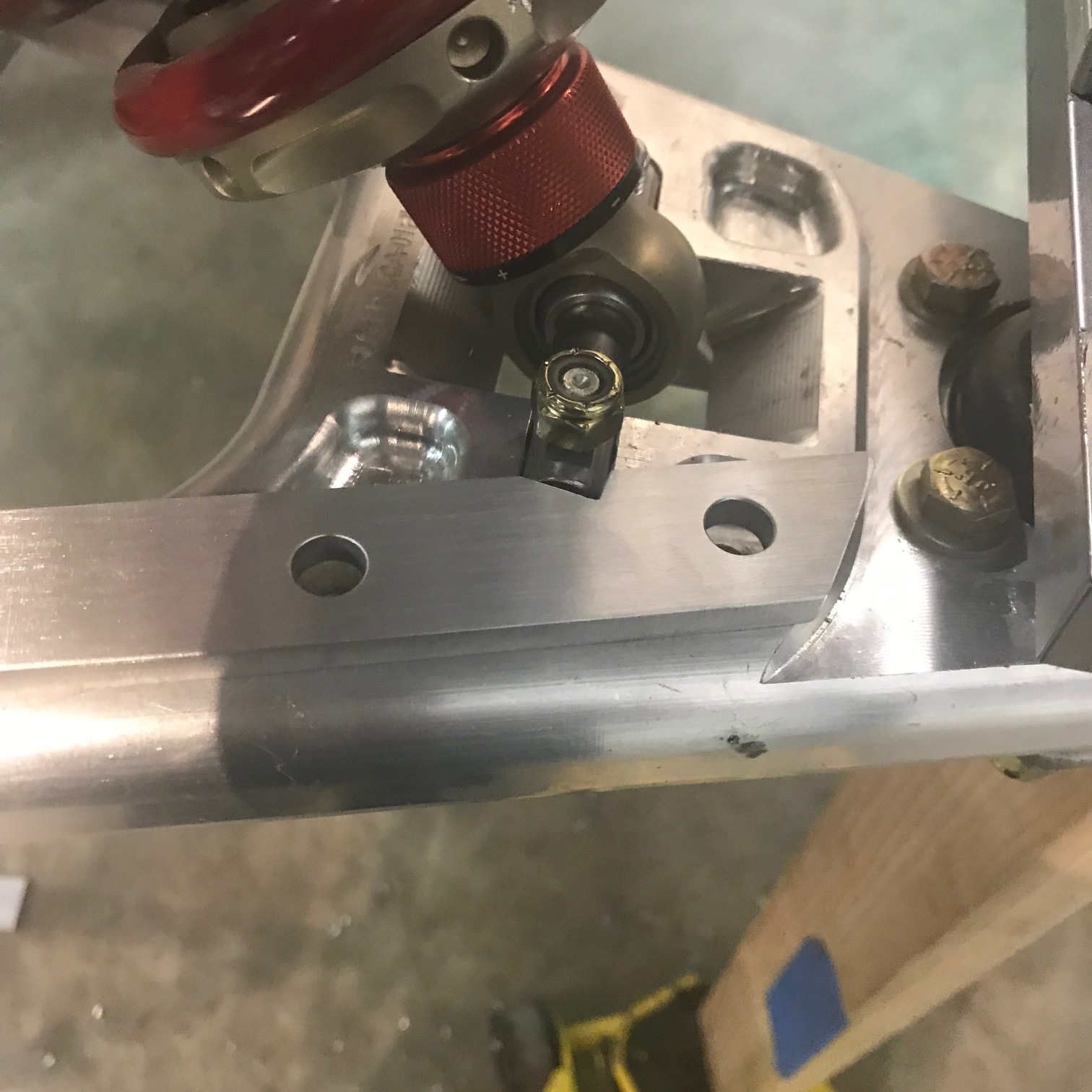
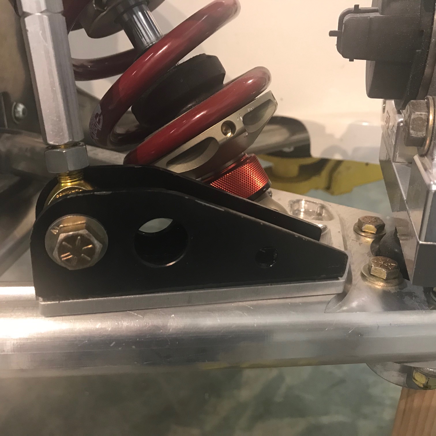
IMO, 1010 is a poor choice for my nose structure due to the small OD, sub-optimal geometry and that one of the primary purposes of the structure is to allow the car to be dragged out of a gravel trap and the recovery hook is at the tip of the frame. I don't want that probable event to result in a deformed structure. Hopefully I never wish that I had a structure that absorbed more energy!

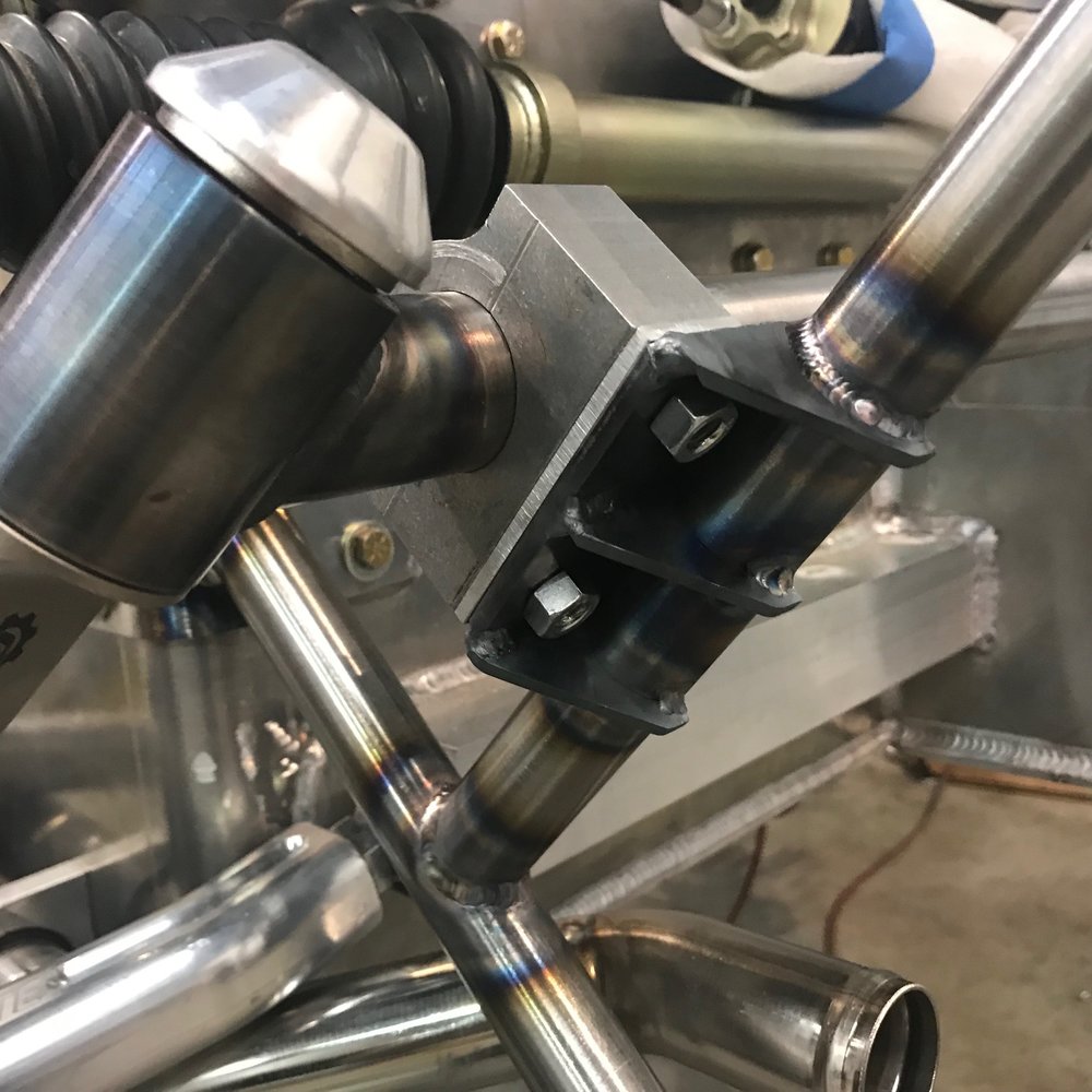
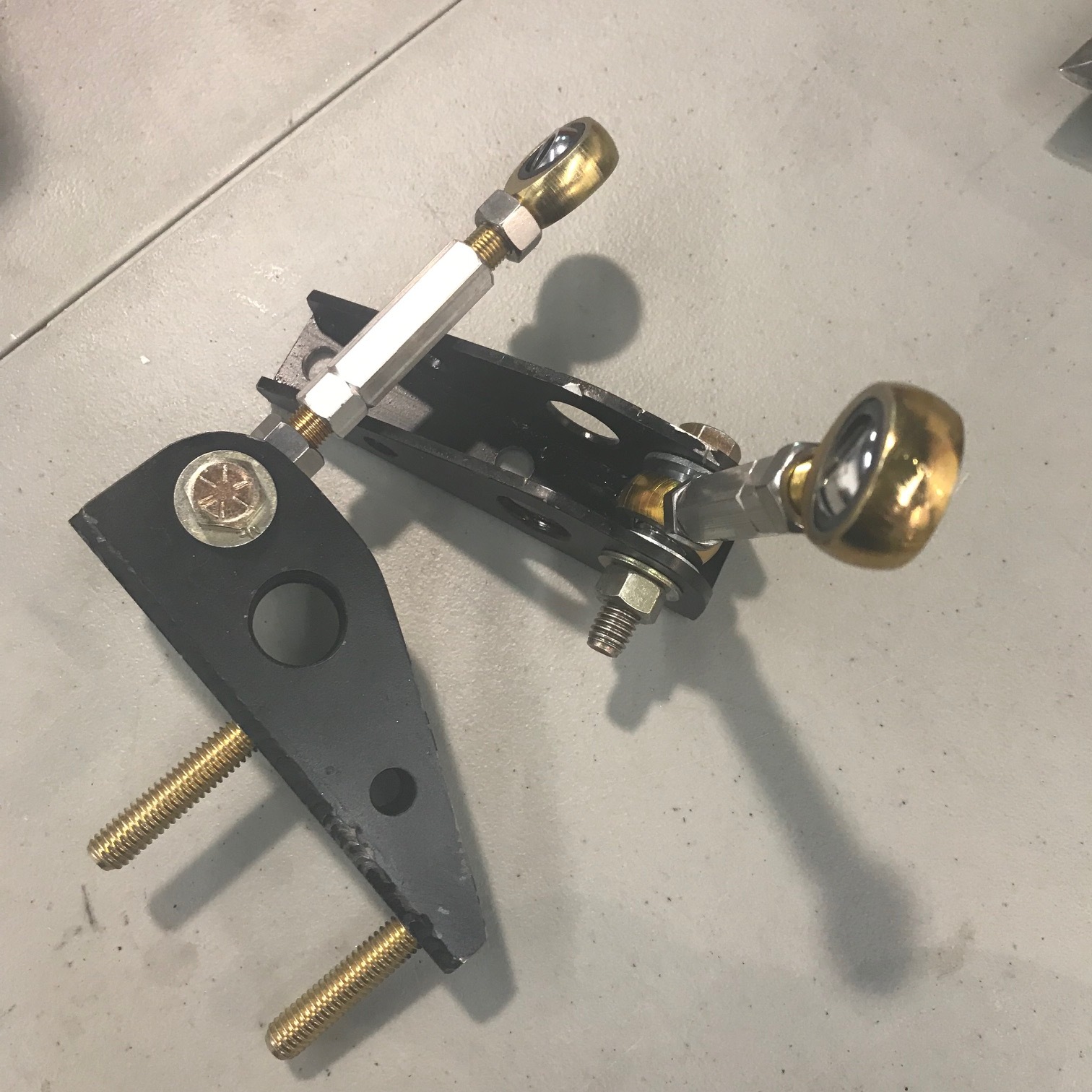
The bracket and tow hook are made from 1/4" cold rolled 1020. The tow hook is just a plywood prototype.
IMG_6825-1.jpg


With respect to the dumb portion of not heat treating 4130 or using TIG rather than the aviation industry standard oxy-acetylene
… there are many TIG-welded 4130 chassis and it seems that few if any are baked in an oven for hours at over 1,000 degrees. For example, the tube version of RCR’s 917 is chromoly and I doubt that it’s heat treated. Apparently, if a professional follows the best practices for TIG welding 4130, there won’t be an issue with brittle joints. That said, to Carroll’s point the 10-20% gain in strength vs. 1020 might not be worth it.
 
Last edited:

Neil

Supporter
Scott;

First, it wasn't a dumb idea at all. Lots of airplanes are flying with 4130N primary structures. I assume that you are using "N". But note that there is a difference between 4130 and 4130N. The "N" signifies that it is in the "normalized" condition. Just "4130" does not. 4130N is a very good compromise between ultimate tensile strength and elongation. The point of 1010, low carbon steel, is that it has a VERY wide plastic range and that is what absorbs energy. It is defined as the "modulus of toughness", the area under the stress-strain curve. Attached is a stress-strain diagram and a table of the modules of toughness for some materials. I was not able to find comparable data on 4130N unfortunately. The strain rate is another complicating factor. The curves change depending on how suddenly the stress is applied; in a crash it would be different than for a slowly applied stress. Also, it is best to avoid hot-rolled mild steel; cold-rolled or cold drawn is preferable.

In any case, the 4130 in your nose structure will work OK. In a frontal crash it will probably fail in bending where the tubing is already bent. Someone once referred to bent tubing as "a pre-buckeled structure". All straight tubing sections are stronger but bent tubing chassis are still quite common. One way to improve the strength and stiffness of your nose structure would be to make the vertical side panels out of thin 4130N sheet steel and weld them to the tubing. Adding a stressed panel across the bottom would also be a good addition.

Both 4130N and 1010 weld very well. If your weldor finds that 1010 has more impurities the quality of the material is suspect.

Ideally, you want the chassis to deform in a crash (absorbing energy) but not so much that it intrudes into the driver's space. The more kinetic energy that is absorbed, the less is transmitted to the driver.

Please take these suggestions/comments as friendly suggestions, not as criticism. Your workmanship is exemplary.
 

Attachments

  • Strain.jpg
    Strain.jpg
    88.2 KB · Views: 314
  • Toughness.jpg
    Toughness.jpg
    292.1 KB · Views: 272

Howard Jones

Supporter
I have had my SLC towed off the track and I can tell you that the tow vehicle worked "quickly" and without regard to the perceived strength of my tow hook. So I recommend the following.

The general tube structure is fine as well as the hook itself. My concern is the triangulation of the complete structure. Think about a tow rope stretching and the truck pulling you around a tight 90 degree corner leaving the track. This puts a force into the structure at nearly 90 degrees to the hook plane at the hook. In this case there is a lot of lever length because the pivot point is all the way back at the foot box vertical wall. What you do not want is the radiator to form the triangulation and be subjected to the forces being generated. I think either the floor of the nose box or a front corner to rear opposite corner tubing element needs to be added that is strong enough to prevent the whole box from deforming.

You might be able to bolt the floor to the tube frame in at least 4 places to accomplish this. Two in front and two at the rear As far apart as possible. Or a piece of 1 inch square tubing might be attached across the bottom of the whole thing to do the same thing.

I don't want to see your radiator damaged by the tow truck. By the way I really like the stuff you have done. Some really nice work. Keep it up.
 

Scott

Lifetime Supporter
Niel, I asked my fabricator about his "purity" comment. Apparently like grade 8 bolts and Bosch 044 pumps there is a fair amount counterfeit Chromoly. So he only purchases certified Chromoly made in USA from a reliable vendor. One would hope that premium, certified, domestic would have higher purity. He also prefers the way that the extra nickel content wets-out the weld pool. I agree that Carrol isn't gospel, but he you and I all agree cold rolled is the way to go!

Howard, I'm concerned about the exact scenario you describe -- having the car yanked out of a gravel pit at 90-degrees with a . We looked into doing an "X" on the floor between the side bars, but the coolant tubes don't make that feasible. We also looked at doing an "X" between the top bars, but my plan is to cut a big radiator outlet into the nose so that's out. The current plan is: 1" tube between top bars in front of the nose box (position will be determined by the radiator outlet), 1" between the lower bars as close to the radiator as we can get, 4 gussets where the sides meet the bar in front of the radiator, and four 1/4" bolts through each side panel into 1/8" welded tabs. Both you and Niel suggested that I make the make the floor a stressed panel which is an excellent idea. Now that the tubes are in place it's much thicker than it needs to be so I should put that thickness to good use. Hopefully all of that gets the job done.
 

Scott

Lifetime Supporter
My oil cooler will be fed by the left-rear side scoop. The radiator is larger than the opening so my plan is built a simple duct to guide the air. There isn't a whole lot of room between the scoop and the rear wheel liner, but I'm trying to determine the best place to locate it. There are two primary decisions:

1.Location between scoop and tire. I assume that the further the radiator is from the vent, the more the air can expand to cover the whole cooler. I'm also thinking that the rear tire will create a low pressure area and facilitate flow, but maybe that's dead wrong.

2.Angle of the radiator with respect to the side of the car. Air will obviously flow better if the radiator is at the same angle as the duct, but a different angle should work fine if ducted.

Left to my own devices, I will move the cooler as close to the rear wheel well vent as possible and orient is so that it's 90 degrees to the body. Thoughts?
 

Howard Jones

Supporter
The tire will throw everything you can think of into your nice new oil cooler. Leave the shielding in place. Keep it solid. I placed my oil cooler in the same place. Centered in front of the opening and close as practicable. As of now with no ducting. So far the oil is right at 210-220F all through 30 min sessions with air temps in the low 90s high 80s F. If that holds up on a very hot day then I'm not going to add ducting, We will see.
 

Scott

Lifetime Supporter
Howard, for clarification you mounted your cooler close to the tire at 90 degrees to the body, correct? Does "shielding" mean the wheel well liner provided by Superlite and does "keep it solid" mean don't cut slots in it?
 
My oil cooler duct info at this link: https://socalslc.com/2018/09/12/48-duct-duct-goose/

You may have to mount the cooler perpendicular to the body depending on how wide a unit you have. The RCR wheel liners take up a fair bit of space and cuts into the available volume - again, depends on the size of your cooler. I ended up making flat sheet metal lower liners to gain more space, some poor planning on my part but it worked out in the end.

I believe, as with the front wheels, the rear wheels will be high pressure zones and therefore a shield of some type to separate the cooler exit and the tires would help improve cooler efficiency.

Air is going to want to go the path of least resistance so if you want to maximize your cooler’s efficacy some ducting in front would be a good idea. Otherwise I think you’ll lose a lot of airflow above, below, and around rather than going through the cooler - where the air would be most beneficial. I’m sure there’s some magic ratio between opening and cooler surface area but given such a short distance between vent opening and cooler there’s not likely to be much Bernoulli effects happening, it’s all going to be pretty turbulent I think.

Both Howard and I increased the vent opening - the factory opening is a bit small in my opinion, but I also prefer the look of the larger opening.
 

Scott

Lifetime Supporter
The tube frame around the nose box is almost done. As you can see in the picture below diagonal tubes were added to mount the sway bar, four 1/8”-thick tabs were added to each side to mount the vertical aluminum panels, tube gussets were installed where the top tubes meet the monocoque and a 1/8” plate gusset was was added to the tow hook bracket. The next step is to add two tube that connect sides; one on the floor behind the radiator and one at the top near the monocoque and four gussets to reinforce the bar that crosses in front of the radiator.

IMG_6856.jpg


The sway bar’s pillow blocks are mounted to 3/16” steel plates supported by three 1/8” gussets. The Wazer was really useful cutting out the gussets. They’re small and would have been a pain to make by hand. The center gussets are 3/32” shorter than than the end gussets. As you can see if the pictures below, the pre-welding fitment was perfect — just like all of my tube notches LOL. The split collar’s OD was taller than the pillow block’s offset and the were biding on the steel mounting plate. A 1/8” thick spacer solved that issue.
 

Scott

Lifetime Supporter

Tow hook bracket gusset


End gussets on left, middle gussets on right


Sway bar mounting plate welded


Aluminum spacer between pillow block and mounting plate


Gussets welded
 

Neil

Supporter
Scott;

A & A Manufacturing is a good source for tabs and brackets. Purchasing them instead of making them can save you time & effort.
 

Scott

Lifetime Supporter
Neil, thanks for the link. I'm going to build a tube frame for the tail and they might have something I can use. Note that I did purchase 8 tabs for the sides, but I couldn't find any that were appropriate for the pillow block gussets. Once you have pierce time and cut speed dialed in for a given material/thickness, it's really easy to cut parts that precisely fit.
IMG_6854.jpg
 

Scott

Lifetime Supporter
IMG_7079.jpg

The intercooler system needs a reservoir, a way to add coolant and a way to bleed air. I decided to combine all three into a swirl pot. It was a fair amount of work to fabricate the parts and a lot of welding!

While I’m going to hide the stuff I don’t like (e.g. electrical, coil packs, etc.), I want the cool parts of the key systems to be visible. With that in mind I located my super trick oil filter mount to be symmetric with the swirl pot in the rear window. This location accommodates a 5” tall filter element and enables me to easily check for debris through the view port.


IMG_7071.jpg


IMG_7072.jpg


I’m looking for a weld on sight glass like the one shown here for the swirl pot. If you know where to get one, let me know.

viewport.png
 
Last edited:

Scott

Lifetime Supporter
In a previous post I replaced the front sway bar that was mounted to the top of the monocoque with one that’s mounted to the nose tube structure. Although the drop links are a lot shorter, they connect to the lower control arm in the same location. However, I replaced the stock clevis with a custom chromoly bracket. The clevis was mounted with a single bolt that focused the drop link’s forces between the shock mounting pin and the chassis. The bracket distributes these forces outbound towards the hub. It is mounted with two bolts; one closer to the shock mounting pin and the other between the pin and the hub.

The pockets machined into the control arm are great to look at, but they’re a real pain in the ass when you want to mount something because you need to be careful where the holes are located. In particular, you need to avoid the chamfer unless you’re going to machine the hole on a mill. As shown in the picture below 3/8” holes were drilled into the pockets that straddle the shock mounting pin. I fabricated a 1/4” aluminum spacer to pad the bracket above the shock mounting pin (the notch shows where the interfere is). On the underside there is no room in the pocket for a bolt head, let alone a washer, so I fabricated plates out of 1/8” chromoly to span the pockets.

IMG_7111.jpg

Holes drilled in the pockets

IMG_7112.jpg

Spacer notched around shock mounting pin

IMG_7113.jpg

Bracket mounted on spacer

IMG_7117.jpg

Note that bolts shift forces away from the drop link
 
Colin, I plan on making it available to other builders. I'll have to figure out how much... I'll price the same or lower than what it costs to send to one of the 3D print shops. I need to make a couple of tweaks... add a part/version number, add a strain relief for the wire, and a couple of other tweaks. If someone is interested in giving v1.0 a whirl PM me.

Not sure if this offer still stands, but I definitely need to shorten the wiper stalk so I can access the buttons on the side of the screen. You can name your price, it really is a necessity (at least for me).
 

Scott

Lifetime Supporter
Del, the offer still stands... the right stalk definitely doesn't work with the center binnacle. I'm printing a switch module now and I have a spare wiper switch that I'll install. I will send you a PM with the details tomorrow or Monday. Funny that you requested this now... just last week I decided to replace the steering rack with one that has a quicker ratio. That's going to require electric power steering and a new column, so I'm glad I spent all that time trying to refine this part! At least someone will benefit.

Mesa, thanks for the encouragement. At this rate I'm going to have as much customization as you did.

I'd very much appreciate it! It'll make things look good/normal with a new switch. I don't have much seat time, but the stalk doesn't bother me visually (yet), but accessing the volume buttons is tricky with it and that's just with the car parked!

Please send me PM when you get some time, I'm definitely in! Thank you sir!
 
Back
Top