Man that thing is looking sweet. Nice progress.

You are using an out of date browser. It may not display this or other websites correctly.
You should upgrade or use an alternative browser.
You should upgrade or use an alternative browser.
Sean Starkey
Lifetime Supporter
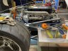
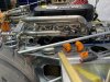
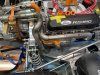
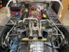
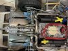
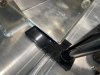
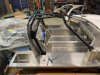
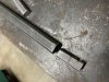
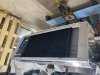
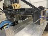
This ICEngineWorks mock up kit is great. I have most of the right side headers tacked up. It isn't as hard as I expected to be, but the mock up kit did help a lot. So far I have been able to keep the lenght very close to equal, but I am not sure If the left side will work out as well.
Attachments
-
 IMG_5918.JPG517.4 KB · Views: 1,100
 -
 IMG_5919.JPG549.9 KB · Views: 1,083
 -
 IMG_5938.JPG505.6 KB · Views: 957
 -
 IMG_5939.JPG583.7 KB · Views: 952
 -
 IMG_5940.JPG484.9 KB · Views: 893
 -
 IMG_5942.JPG528.5 KB · Views: 840
 -
 IMG_5944.JPG518.7 KB · Views: 836
 -
 IMG_5948.JPG503.4 KB · Views: 830
 -
 IMG_5964.JPG561.6 KB · Views: 983
 -
 IMG_5965.JPG516.7 KB · Views: 930
Sean Starkey
Lifetime Supporter
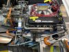
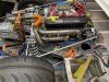
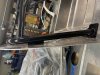
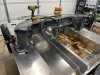
I figured I would share a few more pictures of the header progress. Im waiting on some more mandrel bends to arrive to finish them off. As I suspected I will have slightly unequal length on the left side. Im putting more importance on how it looks vs having them equal length.I still need to finalize how I am going to run #7 I don't like the mock-up I did, but overall they are coming out quite nice.
Attachments
Rod Dittmar
Supporter
Sean,
Very nice indeed! I wish I had the skill to do that. Actually, I'm not sure if I have the skill or not....I just don't have the patience to try and find out. Anyway, your car is looking great.
Very nice indeed! I wish I had the skill to do that. Actually, I'm not sure if I have the skill or not....I just don't have the patience to try and find out. Anyway, your car is looking great.
Sean Starkey
Lifetime Supporter
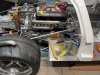
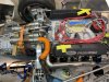
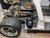
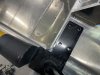
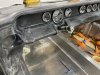
Now that Covid is behind me, I was able to get the header fitment completed. I still need to weld them out and ceramic coat them. I really like the way they turned out.
Attachments
Sean Starkey
Lifetime Supporter
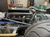
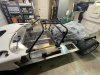
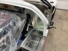
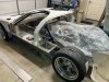
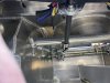
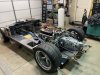
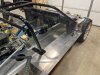
I mounted the roll cage and firewall today. As you can see, the roll cage needed quite a bit of encouragement with a port-a-power and a ratchet strap to be centered in the chassis and match up to the angles on the firewall. I found that the assemblers at RCR didnt pay close attention when they mounted the firewall, I had to slot the holes they mounted it with 3/8" to level the firewall on the right side.
Attachments
-
 IMG_6041.JPG487.9 KB · Views: 783
 -
 IMG_6042.JPG402.1 KB · Views: 763
 -
 IMG_6043.JPG432.7 KB · Views: 764
 -
 IMG_6044.JPG470.6 KB · Views: 754
 -
 IMG_6045.JPG501.8 KB · Views: 763
 -
 IMG_6046.JPG480.8 KB · Views: 724
 -
 IMG_6047.JPG399.8 KB · Views: 717
 -
 IMG_6050.JPG422.1 KB · Views: 728
 -
 IMG_6051.JPG479 KB · Views: 757
 -
 IMG_6053.JPG459 KB · Views: 820
Sean Starkey
Lifetime Supporter
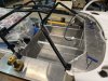
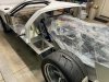
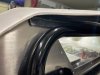
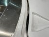
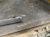
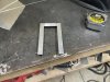
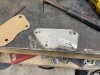
I am curious about this lip on the spider where it mounts to the firewall. Ive seen several mention it mounts to the front of the firewall, but this seems to push the spider too far forward on the chassis to achieve the 35mm sugested from the spare tire well by RCR. If i put it behind the firewall, I would have to reshape the aluminum firewall for it to sit all the way down on the chassis.
Does anyone have some insight on this?
Does anyone have some insight on this?
Attachments
Sean Starkey
Lifetime Supporter
I am curious about this lip on the spider where it mounts to the firewall. Ive seen several mention it mounts to the front of the firewall, but this seems to push the spider too far forward on the chassis to achieve the 35mm sugested from the spare tire well by RCR. If i put it behind the firewall, I would have to reshape the aluminum firewall for it to sit all the way down on the chassis.
Does anyone have some insight on this?
Bill from RCR reached out to me to let me know this lip was supposed to have been removed. I took it off and it is sitting much better now.
Sean Starkey
Lifetime Supporter
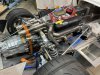
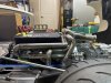
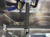
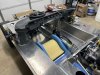
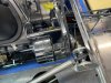
I was able to get the suspension set up using RCRs recommended settings. I end up with 94 9/16" wheel base, I am pretty happy with that. I followed Tom's detailed setup for this, link here: https://www.gt40s.com/threads/toms-rcr-40-trackracer.24525/ I was surprised to see most of my measurements were the same.
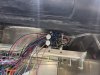
I got the steering set up and dash fitment underway. I found there is a hole under the dash I thought was for the hiem joint to hold the DD shaft. I am assuming it must be for a different rack setup or something else entirely. If you use it the steering column will end up at an extreme angle. I made everything square with how the dash will fit and made the the shaft straight in line with the rack. Then measured and drilled a hole slightly offset to the one in the chassis. I plan to get a PTFE rod and drill 2 holes in the DD shafts to hold them for the collapsable part. This will prevent the shaft attached to the steering wheel from pulling out, yet still allow it to collapse if needed ( I hope its never needed). I also notched the DD shafts at the ujoints with an end mill to keep them locked in.
The RCR gauges look really nice. I like how they mount with a threaded nut on the back side and wiring is made very simple. I will post more pictures of the dash as I get further along with it.
the little guy had to take it for a test drive to make sure the steering was acceptable. I was glad to hear it passed his standards.
Attachments
-
 IMG_6106.JPG460.7 KB · Views: 755
 -
 IMG_6107.JPG613.3 KB · Views: 766
 -
 IMG_6108.JPG414.1 KB · Views: 785
 -
 IMG_6132.JPG510.5 KB · Views: 788
 -
 IMG_6133.JPG473.2 KB · Views: 781
 -
 IMG_6134.JPG374.6 KB · Views: 782
 -
 IMG_6135.JPG371.1 KB · Views: 767
 -
 IMG_6136.JPG362.7 KB · Views: 766
 -
 IMG_6137.JPG390.1 KB · Views: 757
 -
 IMG_6139.JPG407.3 KB · Views: 791
Sean Starkey
Lifetime Supporter
I was able to get a lot done over the long weekend due to the snow we got here.
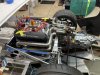
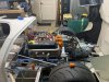
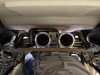
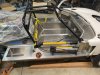
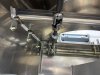
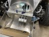
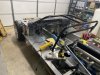
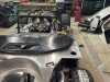
I didn't like how long the supplied shifter handle was, so I removed 2" from it. It feels much better now. I ran the cables to see how the shifting feels, although I will have to remake the brackets when I shorten the nose cone on the transmission. Shifting feels a bit spongy due to the bracket flexing. I was not able to connect the support to the transmission, so I am sure that's all that is needed to tighten it up.
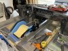
I got the Brakes, pedals, and reservoirs mounted up, also all the brake lines run. Fabricated a bracket to hold the AC condenser, just need to replace the fasteners as I used what i had available.
I didn't like how long the supplied shifter handle was, so I removed 2" from it. It feels much better now. I ran the cables to see how the shifting feels, although I will have to remake the brackets when I shorten the nose cone on the transmission. Shifting feels a bit spongy due to the bracket flexing. I was not able to connect the support to the transmission, so I am sure that's all that is needed to tighten it up.
I got the Brakes, pedals, and reservoirs mounted up, also all the brake lines run. Fabricated a bracket to hold the AC condenser, just need to replace the fasteners as I used what i had available.
Attachments
-
 IMG_6165.JPG285.4 KB · Views: 740
 -
 IMG_6166.JPG462 KB · Views: 711
 -
 IMG_6167.JPG317.2 KB · Views: 717
 -
 IMG_6169.JPG535.2 KB · Views: 739
 -
 IMG_6186.JPG551.5 KB · Views: 724
 -
 IMG_6187.JPG496.7 KB · Views: 716
 -
 IMG_6188.JPG447.8 KB · Views: 698
 -
 IMG_6189.JPG372.7 KB · Views: 702
 -
 IMG_6191.JPG438.5 KB · Views: 724
Sean Starkey
Lifetime Supporter
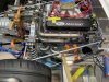
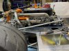
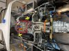
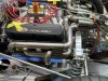
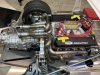
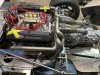
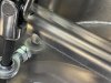
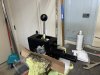
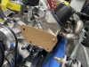
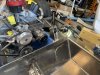
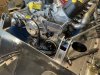
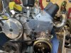
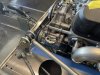
Alternator issue was fixed with a shorter belt, but still very close. I haven't tried to fit up the A/C compressor yet, but I am sure it is going to be a bit of a challenge too with this 351W block.
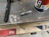
I cut out the dash to fit the roll cage. I over thought how to do this for a couple days until I realized it was a couple quite simple measurements, I wish I had taken pictures to show everyone. But basically just needed to measure where the top front corners of the dash are located, then reference the edge of both the dash and the roll bar with a plumb bob to the body. This let me know where to make the cut to separate the dash, then i just needed to sand away to match the curve and angle of the roll bar. Having the roll bar installed with the seat in it brought up another issue. The center bars are way too close to my head. I am planning on moving them both closer to the center of the car and angle them back out for support on the front.
I fabricated a bracket to hold my fuse block in place. First time welding Aluminum, I'm happy with the results.
Attachments
Sean Starkey
Lifetime Supporter
Sean
With the 351 it's tight but the alternator should fit. I notched out the chassis for some extra room but really wasn't necessary.
Phil,
I thought at first I would have to notch it, but found a smaller belt did the trick. I went from a 15405 (40.5") to a 14395 (39.5") now the Only issue is I have to remove the alternator to change it. I ordered a 15400 (40") to see if its better, but if not the way it is now works well and still allows for tension.
*EDIT* If anyone uses a CVF Alternator bracket for a 351W the correct belt size is the 15400, it fits perfectly.
Sean
Last edited:
Sean Starkey
Lifetime Supporter
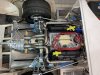
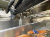
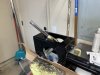
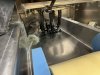
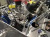
I wasnt able to find an AC compressor bracket that would mount low, so I decided to make one. I made it from 3/16" Stainless flat bar and gave it a slight polish to match the aluminum bits on the front of the engine.
This was the first I got to play with my new plasma cutter, I dont know how I got along without one before.
This was the first I got to play with my new plasma cutter, I dont know how I got along without one before.
Attachments
Chet Zerlin
Supporter
Neil,
My RCR40 has very different brackets. Not sure if these alleviate any concerns?
Chet

My RCR40 has very different brackets. Not sure if these alleviate any concerns?
Chet
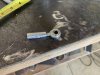
Ian Anderson
Lifetime Supporter
One thing has always bothered me about a rear suspension design like that shown in the last photo. If you crash heavily backwards or if another car rear ends you, that longitudinal upper suspension tube would be a spear pointed at your back.
Discussed previously on this thread.
Chassis Failure
I was running my RCR Lola at a track day at the Circuit of the Americas on July the 5th. Under braking up the front straight entering turn one, the right rear control arm mount tore out of the chassis causing a severe toe-out on that wheel sending the car into a slide. I brought it to a safe...
www.gt40s.com
Ian
Similar threads
- Replies
- 0
- Views
- 439
- Replies
- 46
- Views
- 8K