
- Forums
- GT40 Replica Manufacturers' Corner
- RCR Forum - RCR40/SLC/917/Superlite Aero
- The SLC Clubhouse
You are using an out of date browser. It may not display this or other websites correctly.
You should upgrade or use an alternative browser.
You should upgrade or use an alternative browser.
Stephan's SLC Build Log
New Exhaust System Rev.1, Chapter 2
Passenger side: Final location of the collector and the first welds...
Passenger side: Final location of the collector and the first welds...
Attachments
All I can say Stephan is that you exhaust is going to be a work of art when you are complete. I am in awe of your fabricating skills!
Ken Roberts
Supporter
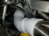
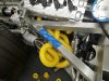
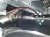
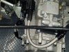
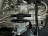
I would reconfigure the stainless braided line from the valley cover to the oil separator. It shouldn't be in the shape of a U. Oil will eventually accumulate at the bottom of the U and seal off the passage. It should be on a slope so that oil that doesn't make it to the separator can drain back to the valley cover. Just my thoughts.I relocated and reconfigured the crank case oil separator and added the transmission vent to it.
Thank you Ken,I would reconfigure the stainless braided line from the valley cover to the oil separator. It shouldn't be in the shape of a U. Oil will eventually accumulate at the bottom of the U and seal off the passage. It should be on a slope so that oil that doesn't make it to the separator can drain back to the valley cover. Just my thoughts.
Both ends on the 10AN are swivel and I could lower the bracket and add a clip to the brace to keep the line horizontal.
New Exhaust System Rev.1, Chapter 3
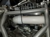
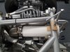
I was able to get the collectors and backwards tubing including mufflers in their permanent places and will soon start with the headers. What a project...
I was able to get the collectors and backwards tubing including mufflers in their permanent places and will soon start with the headers. What a project...
Attachments
Last edited:
New Exhaust System Rev.1, Chapter 4
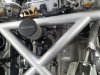
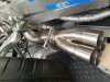
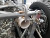
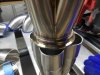
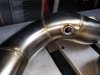
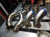
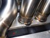
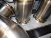
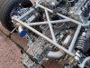
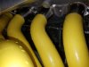
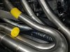
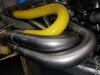
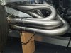
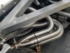
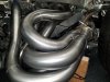
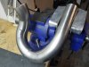
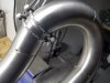
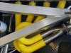
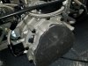
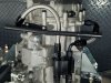
I finished the port matching and adding the Mercury bolt pattern to the new manifolds before mounting them. Now it was time to get serious with a tube layout. A lot to consider when making your own and first tuned exhaust system. I tried a few different ways and focused on being able to remove the headers when the body is on, keeping the weight low and as far inboard as I could. Keeping space between chassis and tubing for the header to grow as it heats up. What material thickness etc, etc... Here is how my headers transforming from theory to reality. I started on the passenger side of cramping 32" of 2" primary equal length 304SS tubing in this car.
I finished the port matching and adding the Mercury bolt pattern to the new manifolds before mounting them. Now it was time to get serious with a tube layout. A lot to consider when making your own and first tuned exhaust system. I tried a few different ways and focused on being able to remove the headers when the body is on, keeping the weight low and as far inboard as I could. Keeping space between chassis and tubing for the header to grow as it heats up. What material thickness etc, etc... Here is how my headers transforming from theory to reality. I started on the passenger side of cramping 32" of 2" primary equal length 304SS tubing in this car.
Attachments
-
 20200421_153654.jpg367.4 KB · Views: 531
 -
 20200421_153900.jpg386.4 KB · Views: 538
 -
 20200325_182628.jpg234 KB · Views: 531
 -
 20200325_182545.jpg333.1 KB · Views: 524
 -
 20200403_124632.jpg241.1 KB · Views: 554
 -
 20200402_193757.jpg458.3 KB · Views: 516
 -
 20200404_153344.jpg371.7 KB · Views: 527
 -
 20200404_183641.jpg297.1 KB · Views: 540
 -
 20200405_170039.jpg369 KB · Views: 531
Last edited:
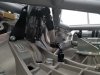
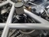
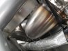
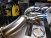
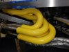
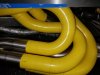
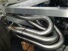
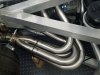
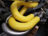
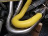
More of the passenger side. So far its only tacked together, I like the layout and probably keep it like that. I used tubing from JMD in California. The best quality mandrels I was able to find. The 180 Degree were chosen in 3",4" and 6"CLR.
Attachments
Last edited:
Hello Joel,Stephan, a work of art. Just beautiful!
As always thank you for the compliment. This is far from being ready but I guess the result is quite encouraging. Many hours of welding still ahead but the driver side is already all tacked up as well and is looking just as nice. I will post more pictures at some point. So far I am having a blast doing this all by myself.
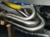
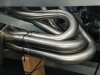
New Exhaust System Rev.1, Chapter 5
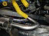
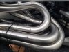
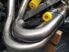
The driver side
The driver side
Attachments
Ron McCall
Supporter
Does that thermostat have a bypass circuit?
Ron
Ron
Ken Roberts
Supporter
Yes it does. Here is a diagram of the inside.Does that thermostat have a bypass circuit?
Ron
Thanks Ken for answering this.
Scott
Lifetime Supporter
Stephan, that's the same one that I have. Note that Daily spec'd a -12 for my oil line and the female threads on the thermostat are only -10. I called Improved Racing and their -12 male fitting provides an unrestricted 0.60" which is 0.02" larger than a standard -12 AN straight hose end.
Steven Lobel
Supporter
Stephan, that's the same one that I have. Note that Daily spec'd a -12 for my oil line and the female threads on the thermostat are only -10. I called Improved Racing and their -12 male fitting provides an unrestricted 0.60" which is 0.02" larger than a standard -12 AN straight hose end.
I noticed that from Daily as well. -16 for the big stuff, -12 for the rest. But the fitting that comes out of the block on mine is a -10. So no matter what, one leg is going to be the bottle neck.
Hello Scott,Stephan, that's the same one that I have. Note that Daily spec'd a -12 for my oil line and the female threads on the thermostat are only -10. I called Improved Racing and their -12 male fitting provides an unrestricted 0.60" which is 0.02" larger than a standard -12 AN straight hose end.
Thanks for the tip. Are you refering to enine cooling? This setup is for transaxle cooling only.
Cheers
Similar threads
- Replies
- 19
- Views
- 4K
- Replies
- 8
- Views
- 4K