
You are using an out of date browser. It may not display this or other websites correctly.
You should upgrade or use an alternative browser.
You should upgrade or use an alternative browser.
Toms RCR 40 Trackracer
- Thread starter EGLITOM
- Start date
- Status
- Not open for further replies.
I hooked up my heater the same way you did and got zero flow through it. The radiator does not present enough resistance to flow to create a driving head for the heater. I had to add a pump dedicated to the heater circuit.
After trying it some time now , i have to say that no additional pump is needed. The
heater works great the way it is hooked up in parallel to the main cooler. The heating system and duction allows to demist the windscreen very nicely
(related to my post #380 on page 19 and Jonathans comment to it)
TOM
Tom
I also find that the heater works fine. However it took a number of driving cycles until it finally worked well. I suspect air in the heater blocked the water flow but eventually dissipated with repeated running and cooling cycles. There is no easy way to bleed air out of the heater given it's location.
With a bit of fall in the air last weekend I used the heater for the first time this season.
Interesting. I went several heat cycles and never got flow through the heater. I even have air bleeds at the high point of both heater hoses to purge air from the heater core.
It even worked from the beginning. I think my expansion tank location and the air bleeds from cooler and intake just minimize any air trapped. I just filled my system, had it stay open overnight and refilled to half level of expansion tank, never had to refill since, level stays the same and everything is working fine
TOM
TOM
FIKSE RACING WHEELS
Received my NT01´s on Friday, my son mounted them on the FIKSE Rims today.
After that i had to had them on the car.
9x17 front with 235/40/17; 12x17 rear with 315/35/17. They fit perfect. The fronts have 1/2 of clearance when steering. I had them made 1/4 " wider to the outside and 3/4" wider to the inside then the BRM´s. Rear are the same offset as BRM´s including the central lock adapter thickness. PCD is the same as on knock off adapters, so it is a true bolt on , just like a standard wheel change.
Weights:
BRM Front 8x15 w 225/50/15 = 19,6 kg +2,5kg(CL-adapter) =22,1kg
BRM Rear 12x15 w 345/35/15 = 26,0kg + 2,5kg = 28,5kg
FIKSE Front 9x17 w 235/40/17 = 19,7kg
FIKSE Rear 12x17 w 315/35/17 = 23,4kg

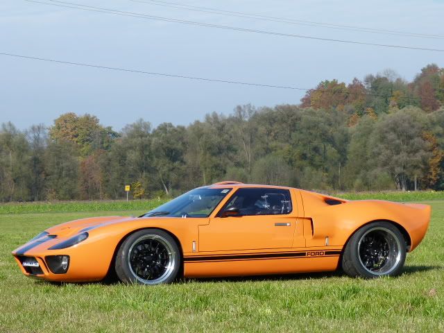
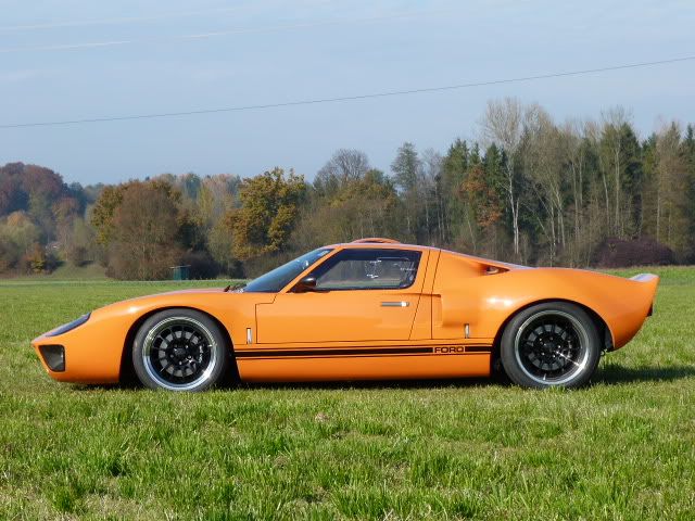
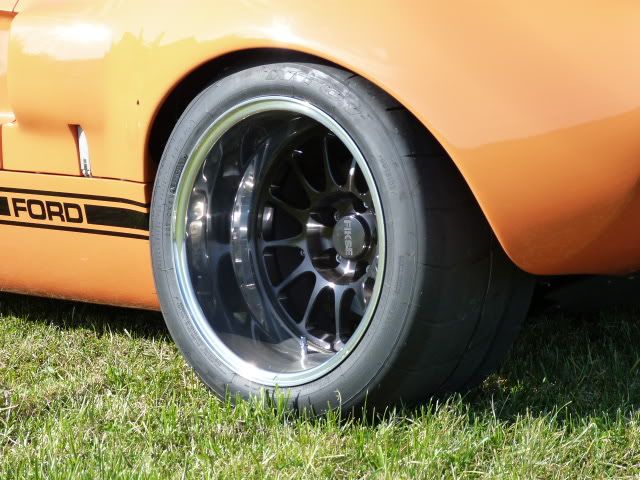
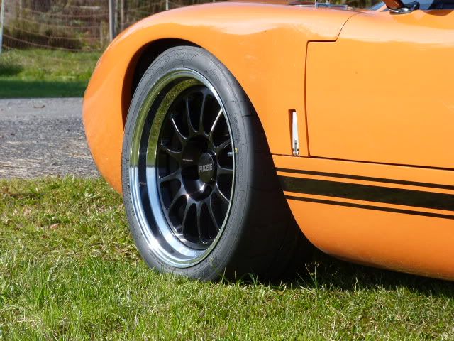
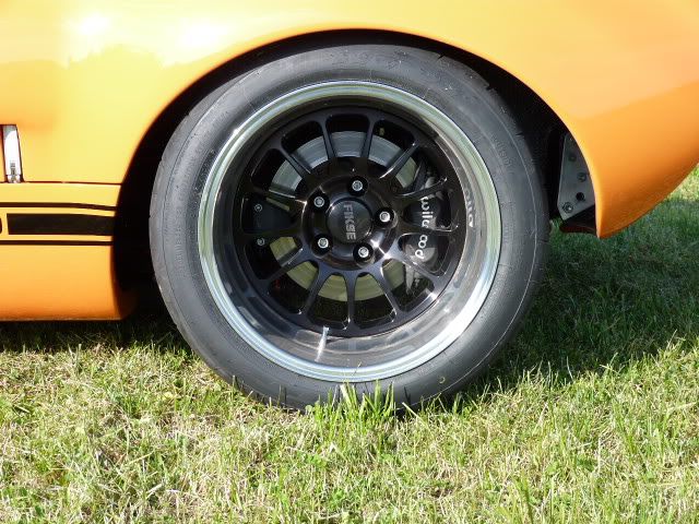
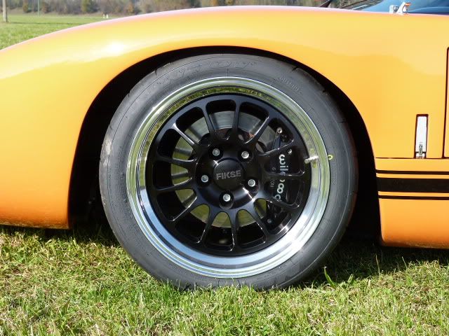
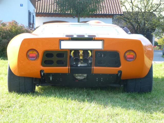
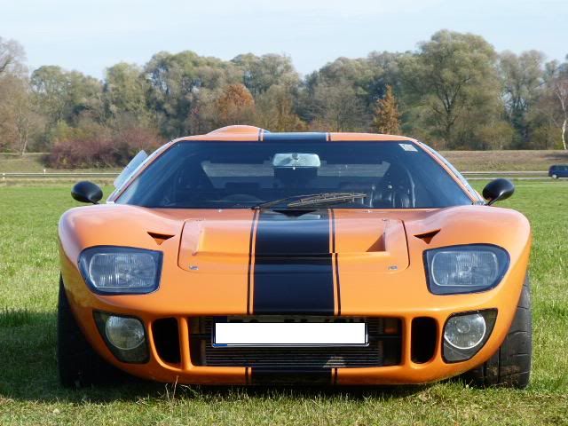
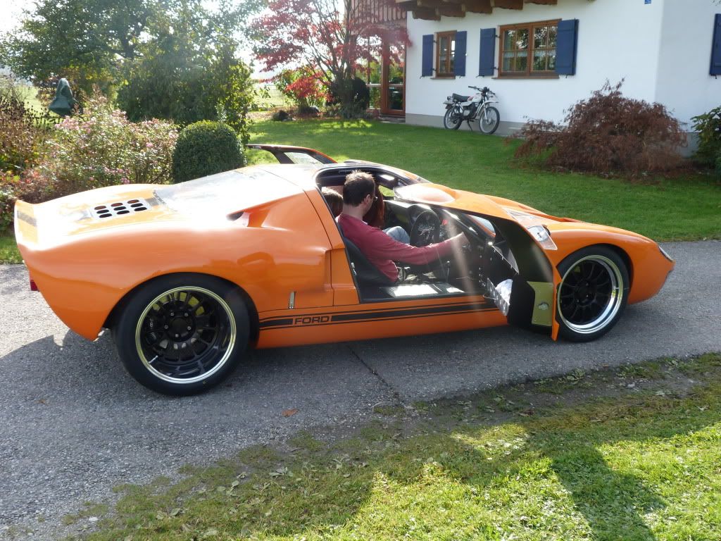
It is impressive how those wheels change the appearance of the car. They actually make it looking like a modern car, thus proving again how timeless the design of the GT40´s is.
TOM
Received my NT01´s on Friday, my son mounted them on the FIKSE Rims today.
After that i had to had them on the car.
9x17 front with 235/40/17; 12x17 rear with 315/35/17. They fit perfect. The fronts have 1/2 of clearance when steering. I had them made 1/4 " wider to the outside and 3/4" wider to the inside then the BRM´s. Rear are the same offset as BRM´s including the central lock adapter thickness. PCD is the same as on knock off adapters, so it is a true bolt on , just like a standard wheel change.
Weights:
BRM Front 8x15 w 225/50/15 = 19,6 kg +2,5kg(CL-adapter) =22,1kg
BRM Rear 12x15 w 345/35/15 = 26,0kg + 2,5kg = 28,5kg
FIKSE Front 9x17 w 235/40/17 = 19,7kg
FIKSE Rear 12x17 w 315/35/17 = 23,4kg
It is impressive how those wheels change the appearance of the car. They actually make it looking like a modern car, thus proving again how timeless the design of the GT40´s is.
TOM
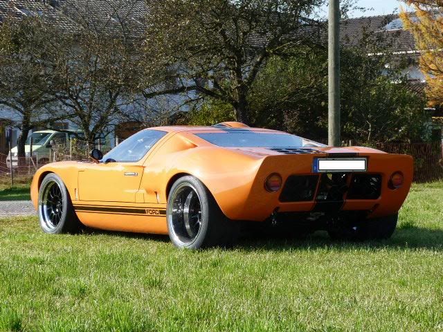
nice pictures Tom, aren't you afraid that those rear wheel act like a leverage? the center lays very in the inside...when you hit a curb then a the load will hit it hard I guess...
As said, this is the very same offset as the BRM´s. Original cars had them 14-15 inch wide . All grown towards the outside. Not saying that this proofs it correct , but that´s the way this cars where.
TOM
Tom,
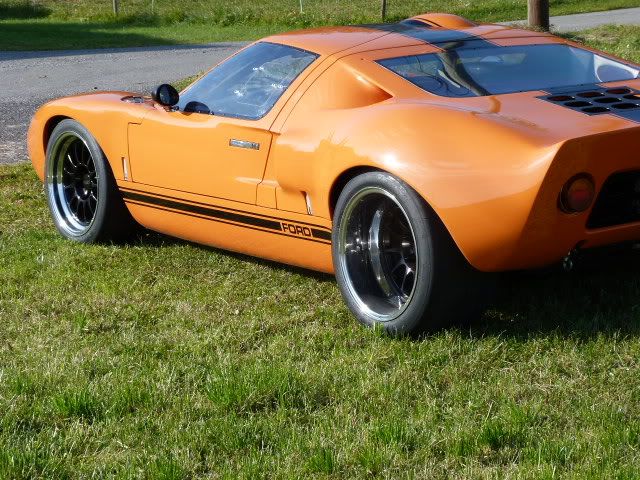
I like those wheels. They offset the orange very well. Having said that.... I am still old school and I think you need to up the aspect ratio on the rears. You need the size to justify the humps of the rear fenders. It does make it loook a little more modern though.
Bill
I like those wheels. They offset the orange very well. Having said that.... I am still old school and I think you need to up the aspect ratio on the rears. You need the size to justify the humps of the rear fenders. It does make it loook a little more modern though.
Bill
Tom,
I like those wheels. They offset the orange very well. Having said that.... I am still old school and I think you need to up the aspect ratio on the rears. You need the size to justify the humps of the rear fenders. It does make it loook a little more modern though.
Bill
Hi Bill
I strictly sized the tires in terms of performance aspects (look came second).
So i looked for DOT legal SEMI SLICKS only, because this is a requirement for the events i want to participate.
One alternative would have been AVON CR06ZZ but i realy felt there usable tread with is to small ( real 185mm ond a 215/60 or real 255m on the 295/50/).
So i came up with the NITTO NT01, which has good references and is reasonable priced.
I checked for the widest front tire i can possibly fit without interference with the bodywork and also with the lowest possible diameter in order to keep the front geometry within the sweet spot, without the need to alter ride heigth. The solution was the 235/40/17. In the rear i looked for the widest available without changing the total diameter to much (total drive ratio) and came up with the 315/35/17.
In this dimensions there are also a lot of other brands to choose from. Toyo R888, Hoosier R6, Michelin Pilot Sport ( in 335/35/17).
TOM
I have never posted how i have done my electrics. Now a cold catched me and i´m laying in my bed having time to do so.
Main battery power is switched via a FIA approved emergency cut off switch which takes off all power once interrupted. Only the charging line from the alternator is still connected to the battery to be able to release the rest of charge into the battery after ermegency cut off. By doing so one have to pay attention to not connect anything to this side of the switch , because this would be a non interuptable connection and therefore still powered.
I started out using the supplied RCR 20 circuit wire loom. It proofed to be the perfect base, because i could use all the circuits. I did separate them in switched power circuits( numbered 30´s) and permanent power cicuits ( numbered 15`s).
Permanent powered circuits are:
I used that much circuits to realy have them independend and thus in case of problems if one circuit the car still will be in running condition.
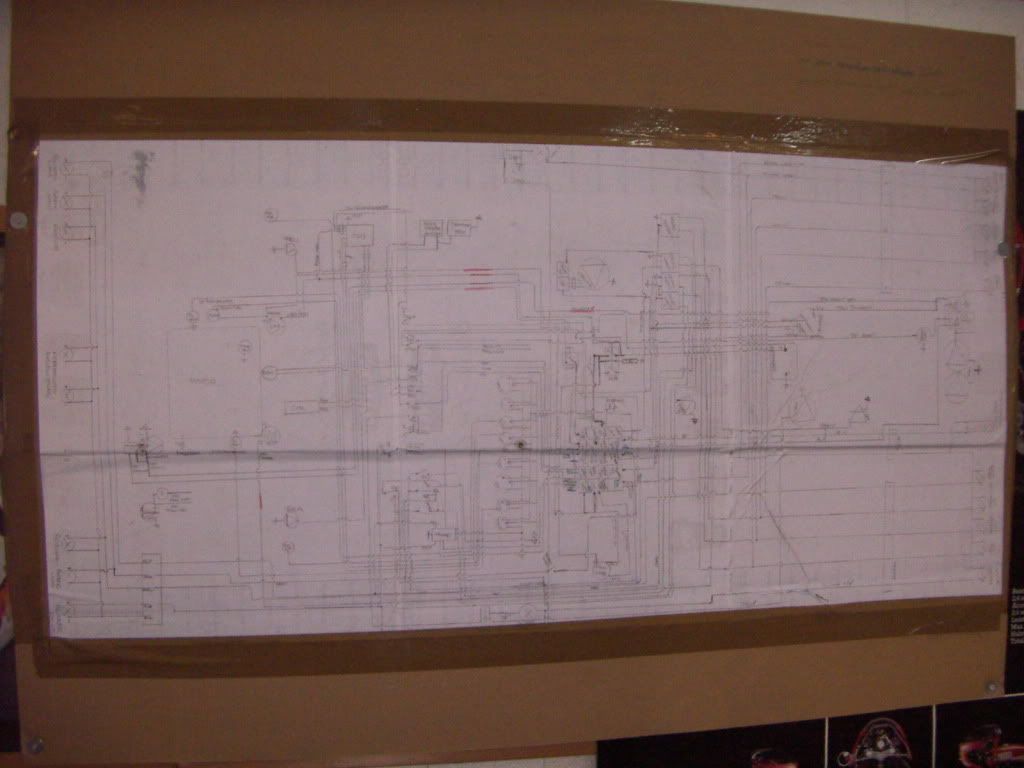
After definition of the circuits i drafted my wiring diagramm. I started to draw each circuit by itself and than combined it to one big diagramm. Took me about 4 h for the single circuits and about 8h for the combination.
Pinned the big diagramm to my garage door and started wiring
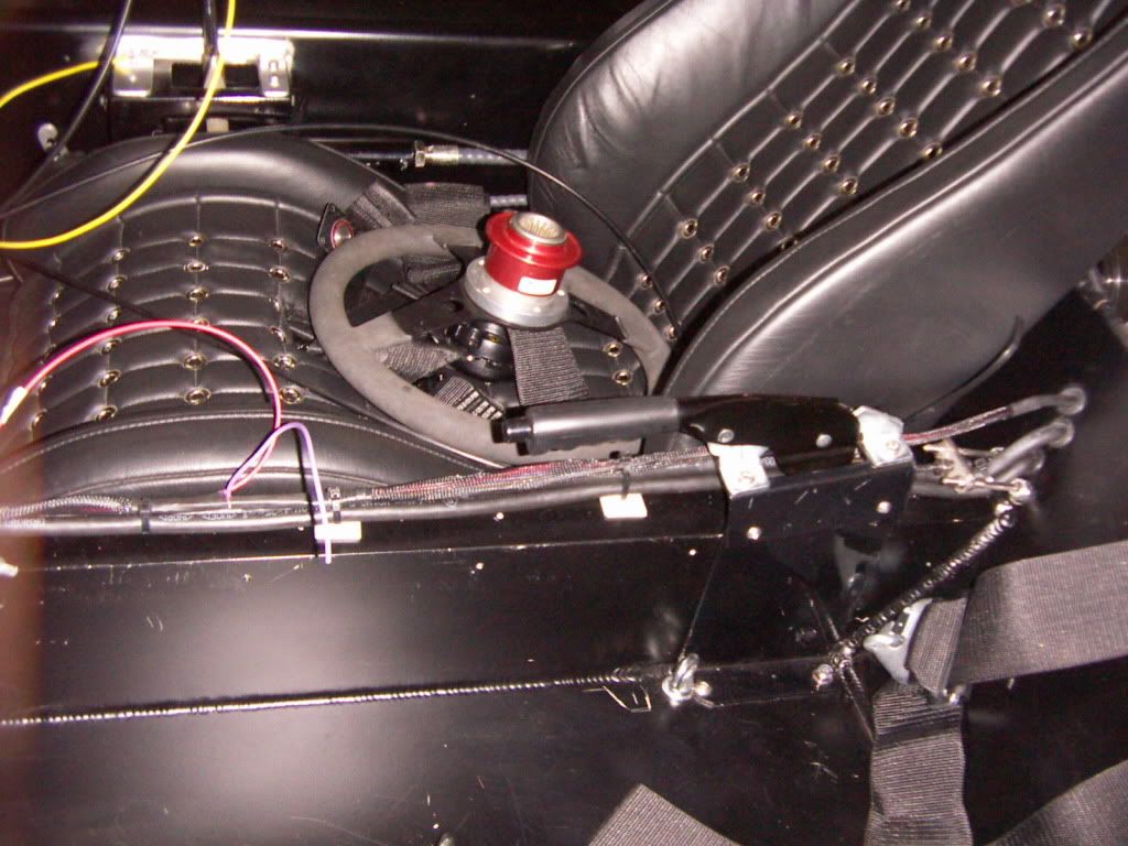
My concept has foreseen two different main wiring routings. The main and heavy power wiring ( alternator to battery, battery to starter, battery to main cut off switch) is routed via the center tunnel .
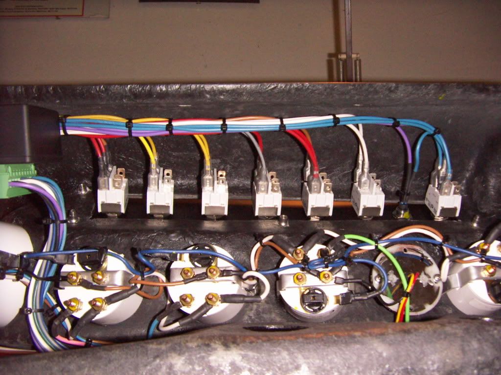
All the other wiring is routed from the fuse box on the center tunnel along the rhd side of the car and is using the Dashboard as main switchboard. I´m using high quality high current switches to minimize the number of relais.
Relais are used for
All wiring is braided with flexibel nylon hoses. Most connections are done with AMP connectors. All connectors are crimped on and additonaly sealed with shrink hose.
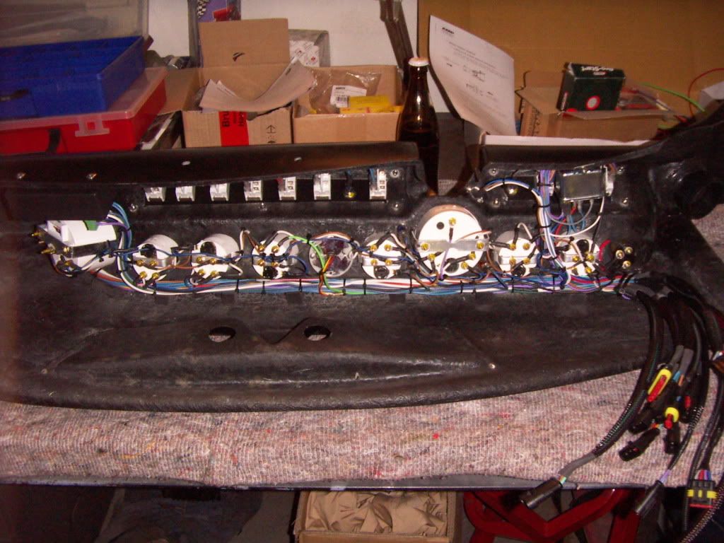
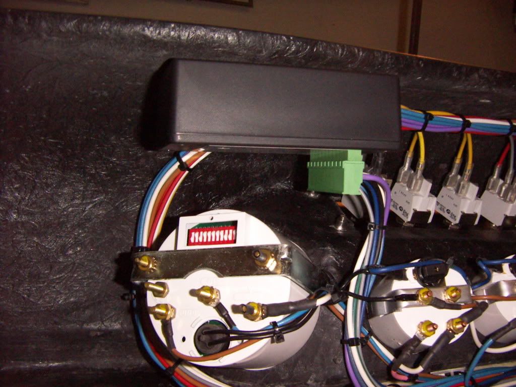
This is the wiring of the dashboard finished
This is the electronic turnsignal controll. It has a timer which deletes the signal. The timer is interupted by pressing the brake pedal . the signal can be stopped also by pressing the other side signal button. If you press on side more than 2 seconds the hazard flashing starts.
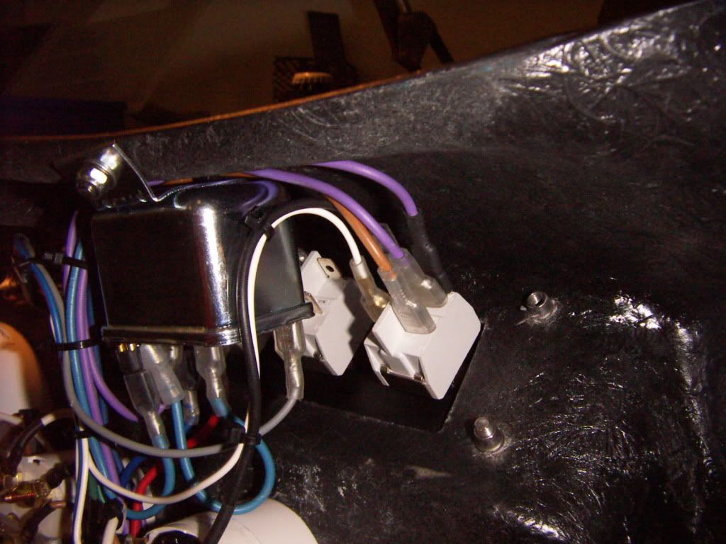
This is the headlight relais. which can be switched by a pushbotton ( not a permanent switch)
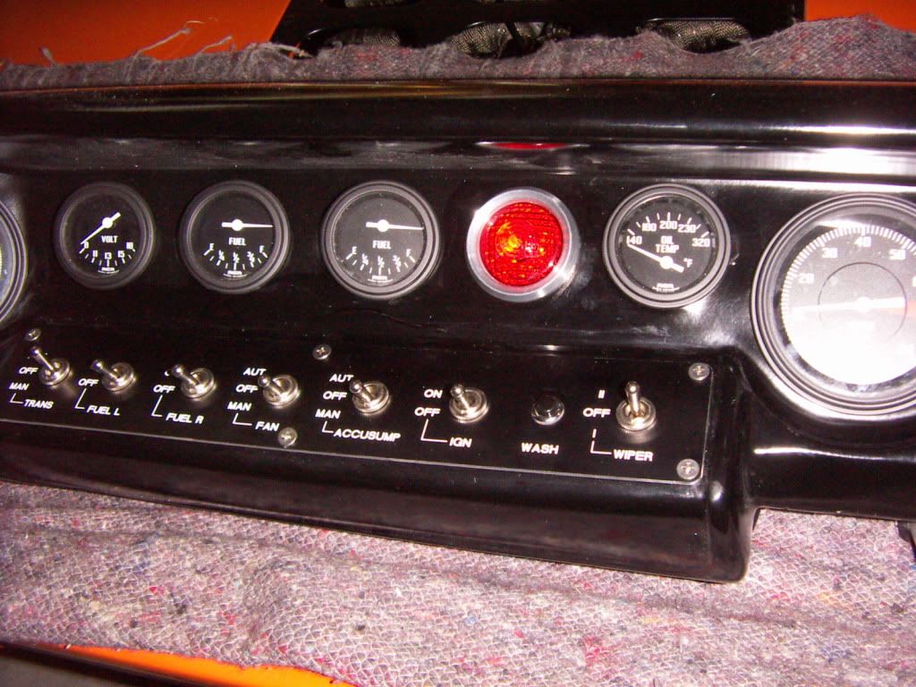
As i have made my dashboard removable , it takes around 20 minutes to disconnect all the plugs, unscrew the dashboard and take it out. The wiring of the switch panels is longer so they can be taken out and serviced separately.
There is a lot wiring going to the switch panels, but i wanted to have everything under control. For example Accusump, Transpump and Fan can be switched off, manual on ( bypassing the thermostat, pressureswitch) and automatic on ( running via thermostat , pressure switch)
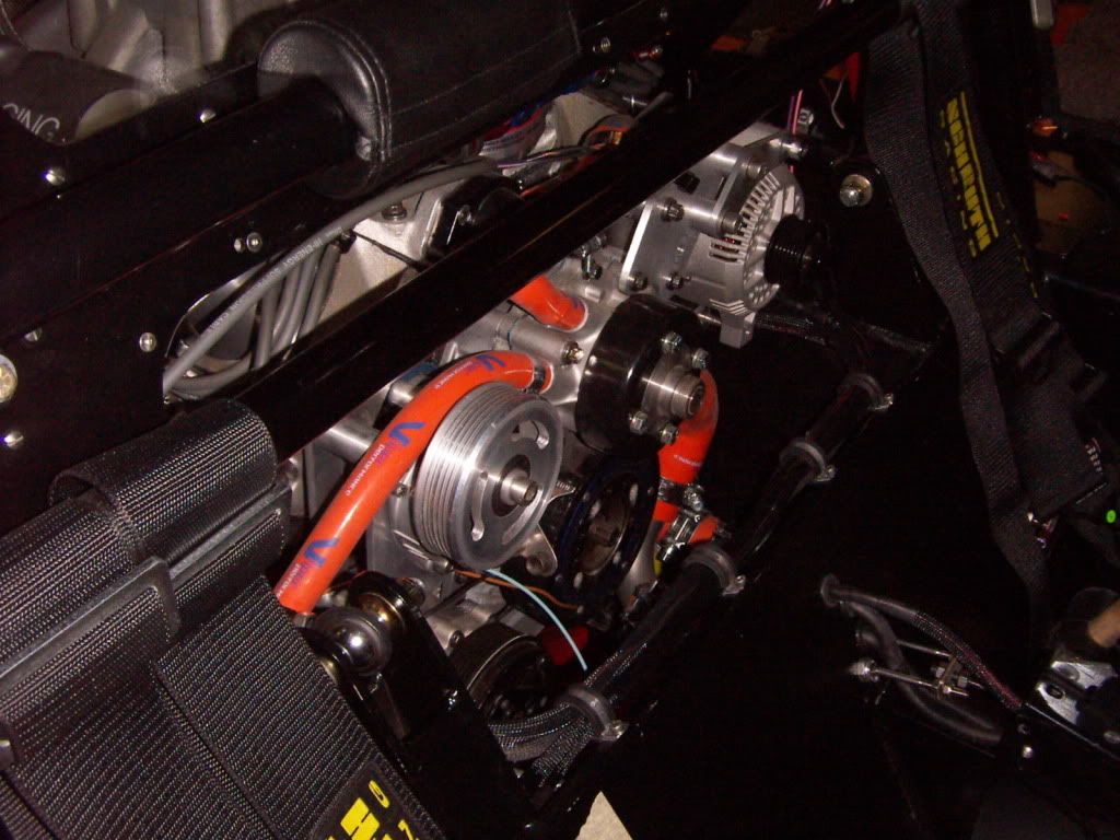
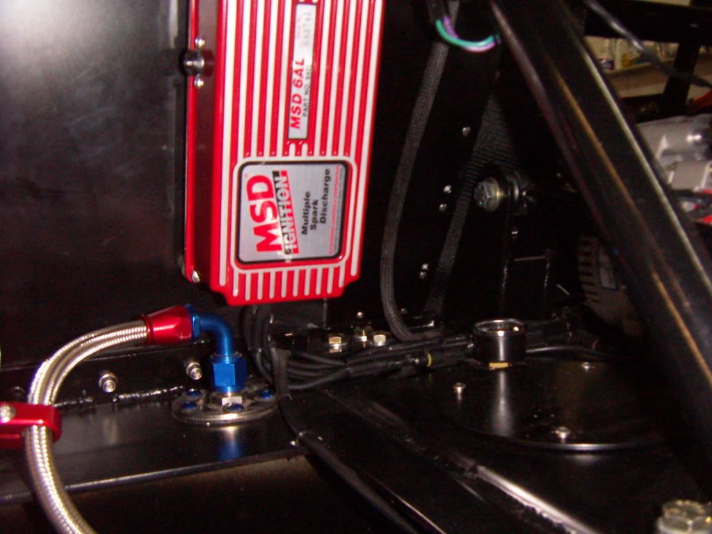
Here are some impressions of the wire routing
wiring across front of engine for ignition, oil pressure, watertemp, lhdside fuel pump, accusump. main power lines from an to battery
Oil pressure sensor and oil pressure warning light
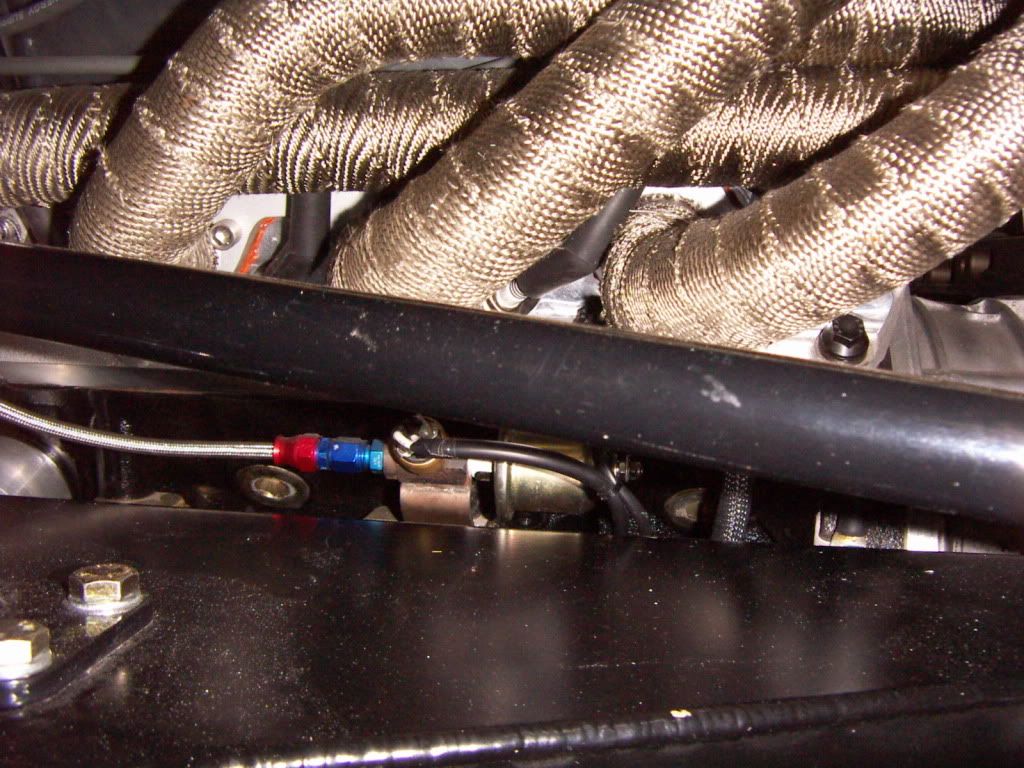
Ignition
Wiring along the RHD side engine towards the rear of the car for rear lights, starter and transcooling pump.
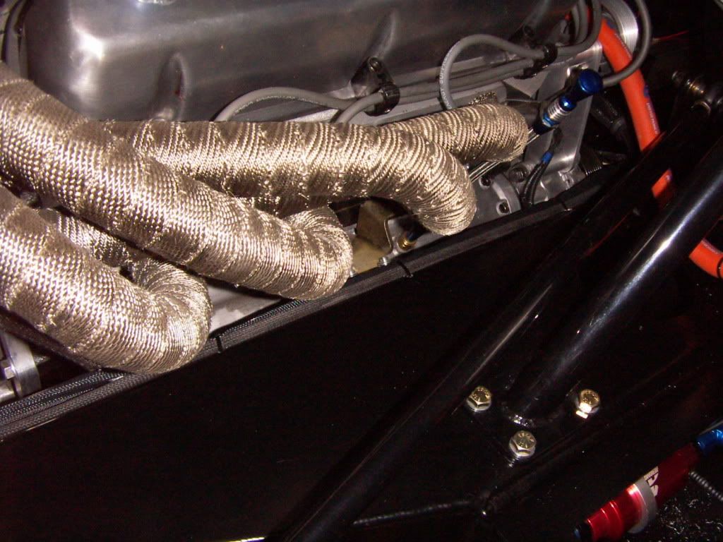
Starter wiring
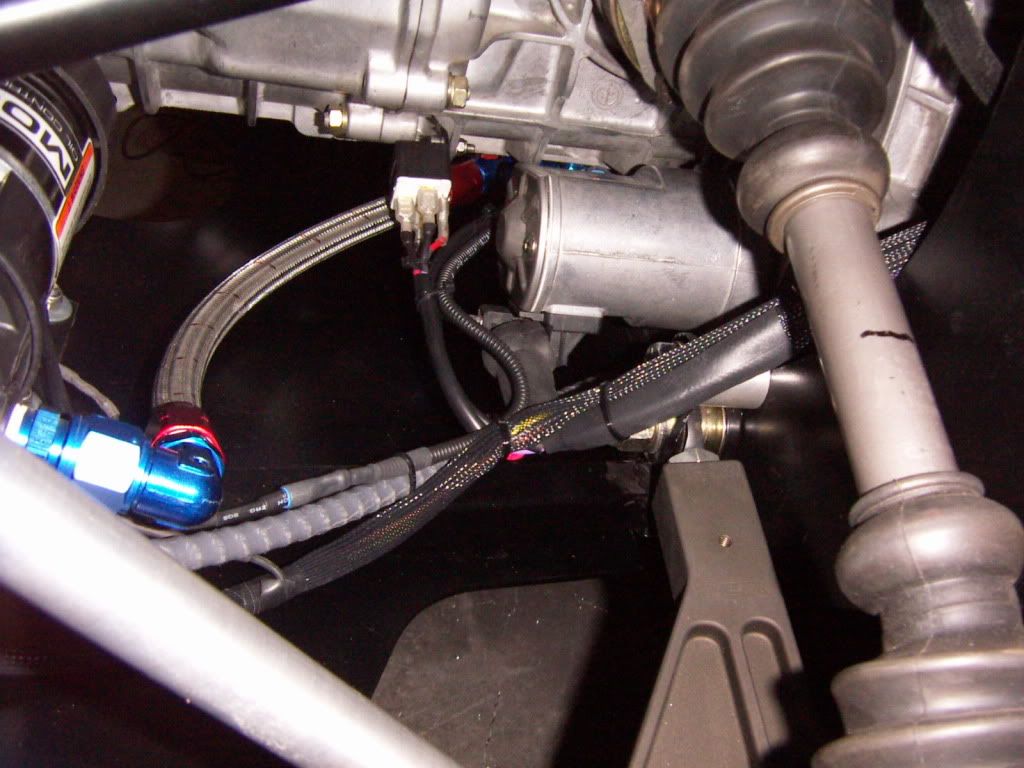
Everything worked perfectly like intended.
THanks
TOM
Main battery power is switched via a FIA approved emergency cut off switch which takes off all power once interrupted. Only the charging line from the alternator is still connected to the battery to be able to release the rest of charge into the battery after ermegency cut off. By doing so one have to pay attention to not connect anything to this side of the switch , because this would be a non interuptable connection and therefore still powered.
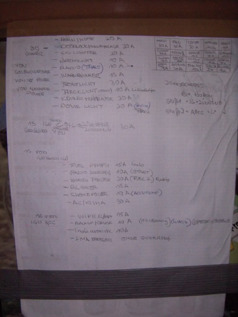
I started out using the supplied RCR 20 circuit wire loom. It proofed to be the perfect base, because i could use all the circuits. I did separate them in switched power circuits( numbered 30´s) and permanent power cicuits ( numbered 15`s).
Permanent powered circuits are:
- Horn 20A
- doorlock ( not connected yet) 20A
- 12 V plug ( cigarette lighter) 20 A
- Transcooling pump ( ex Radio) 10A
- Brakelight 10A
- Hazard Signal 15A
- Headlights 30A
- Rearlights 10A
- Cooling Fans 20A
- Drivelights 20A
- Ignition Coil 30A
- Fuelpump 1 15A
- Starter Relais 10A
- Fuelpump 2 20A
- Turnsignal 15 A
- Accusump control valve 10A
- A/C 30A
- Wiper 15A
- Wash 10A
- Instruments 10A
- Alternator errector (not fused)
I used that much circuits to realy have them independend and thus in case of problems if one circuit the car still will be in running condition.
After definition of the circuits i drafted my wiring diagramm. I started to draw each circuit by itself and than combined it to one big diagramm. Took me about 4 h for the single circuits and about 8h for the combination.
Pinned the big diagramm to my garage door and started wiring
My concept has foreseen two different main wiring routings. The main and heavy power wiring ( alternator to battery, battery to starter, battery to main cut off switch) is routed via the center tunnel .
All the other wiring is routed from the fuse box on the center tunnel along the rhd side of the car and is using the Dashboard as main switchboard. I´m using high quality high current switches to minimize the number of relais.
Relais are used for
- Headlights
- Drivelights
- Cooling fans
- Horn ( because the horn button is a low amp only)
- Starter
All wiring is braided with flexibel nylon hoses. Most connections are done with AMP connectors. All connectors are crimped on and additonaly sealed with shrink hose.
This is the wiring of the dashboard finished
This is the electronic turnsignal controll. It has a timer which deletes the signal. The timer is interupted by pressing the brake pedal . the signal can be stopped also by pressing the other side signal button. If you press on side more than 2 seconds the hazard flashing starts.
This is the headlight relais. which can be switched by a pushbotton ( not a permanent switch)
As i have made my dashboard removable , it takes around 20 minutes to disconnect all the plugs, unscrew the dashboard and take it out. The wiring of the switch panels is longer so they can be taken out and serviced separately.
There is a lot wiring going to the switch panels, but i wanted to have everything under control. For example Accusump, Transpump and Fan can be switched off, manual on ( bypassing the thermostat, pressureswitch) and automatic on ( running via thermostat , pressure switch)
Here are some impressions of the wire routing
wiring across front of engine for ignition, oil pressure, watertemp, lhdside fuel pump, accusump. main power lines from an to battery
Oil pressure sensor and oil pressure warning light
Ignition
Wiring along the RHD side engine towards the rear of the car for rear lights, starter and transcooling pump.
Starter wiring
Everything worked perfectly like intended.
THanks
TOM
Last edited:
Tom,
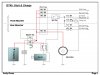
On my circuit design, the alternator is loaded through a 3.3ohm ballast resistor, (via a separate set of contacts in the switch) when the FIA approved master switch is opened.
Attached is one of the diagrams I prepared so hopefully it will all work
Regards
Andy
On my circuit design, the alternator is loaded through a 3.3ohm ballast resistor, (via a separate set of contacts in the switch) when the FIA approved master switch is opened.
Attached is one of the diagrams I prepared so hopefully it will all work
Regards
Andy
Attachments
Andy
I´have wired the resistor in the same way as you additionaly.
On another note i think your breaker will not work and is wired risky if you following your diagramm.
First
It will not break. The only two things your are breaking is the "ecu battery feed" and the "battery feed" itself. If the engine is running the alternator will continue to feed everything, thus everything will keep on running( assumed your ecu is running on ign feed only as well).
But there is an easy fix.
run your charge line from M3-70A directly to the battery not running it via the breaker switch and feed everything via the strong contacts of your breaker switch.
If your ecu is running on ignition feed only as well ( as assumed above), use the small contacts for breaking the "ecu ignition feed " ( don´t use the ecu battery feed at all if possible, or feed it via the "ecu ignition feed" as well) . If you do so you could avoid any current peaks, which still could be created by the breaker routine, entering and destroying your ecu.
Second: ( and thats the real risky thing)
Do not run your starter feed line via the breaker switch, they are not made for that high currents. Run it directly fron the battery to the starter. There is no need to break the starter line. It will not feedback any power into the system because it is broken by the starter solenoid (only in starting mode there will be a feedback into the system) anyway.
TOM
Last edited:
Hi Tom,
Get well soon!!! As I can't wait to meet you in person end of Feb.! I hope I can take a few days off and fly home when you arrive with the car.
On the other hand when I see all the craftmmanship and brilliance you put in the car I am getting doubt if I am gone make it at all.
Cheers
reto
Get well soon!!! As I can't wait to meet you in person end of Feb.! I hope I can take a few days off and fly home when you arrive with the car.
On the other hand when I see all the craftmmanship and brilliance you put in the car I am getting doubt if I am gone make it at all.
Cheers
reto
- Status
- Not open for further replies.
Similar threads
- Replies
- 46
- Views
- 9K